6-32
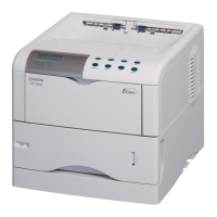
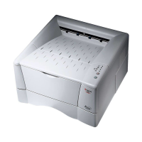
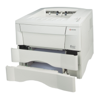
FS-1900
Connector
Pin#
Signal
I/O
Voltage Function
YC205 6 OPSEL0 O 0 V/5 V DC Option unit identify signal 0
7 OPSDI I 5 V/0 V DC
Serial communication data signal with option unit
8 OPSEL1 O 0 V/5 V DC Option unit identifying signal 1
9 OPSDO O 5 V/0 V DC
Serial communication data signal with option unit
10 OPSEL2 O 0 V/5 V DC Option unit identifying signal 2
11 OPRDY* I 0 V/5 V DC Option unit, Ready/Not ready
12 GND - - Signal ground
YC206 1 +24V2 O 24 V DC Power supply for engine relay board
2 +3.3V1 O 3.3 V DC Power supply for LCD controller board
3
MPFSOL*
O0 V/24 V DC MP tray feed solenoid, On/Off
4
FPDATA
I/O 3.3 V/0 V DC LCD controller board data signal
5 MIDDR* O 0 V/24 V DC Middle feed clutch, On/Off
6FPDIR I 3.3 V/0 V DC LCD controller board
7 +24V2 O 24 V DC Power supply for engine relay board
8 FPCLK I
3.3 V/0 V DC (Pulse)
Communication data clock signal
9 GND - - Power/Signal ground
10 GND - - Power/Signal ground
11 FEDDR* O 0 V/24 V DC Feed clutch, On/Off
12 FPRST* O 3.3 V/0 V DC LCD controller board reset signal
13 +24V2 O 24 V DC Power supply for engine relay board
14 FANDR O
24 V/15 to 16 V/0 VDC
Cooling fan motor, Speed control High/Low/Stop
15 REGDR* O 0 V/24 V DC Registration clutch, On/Off
16
MMOTON*
O0 V/5 V DC Main motor, Drive/Stop
17 GND - - Power/Signal ground
18
MMOTRDY*
O0 V/5 V DC Main motor, Ready/Not ready
19 +5V3 O 5 V DC Power supply for laser scanner unit
20
SAMPLE1*
O
0 V/5 V DC (Pulse)
Laser power data sample and hold control signal
Data Sampling/Not sampling
21
POWCONT
O0 V/5 V DC Laser power level control signal,High/Low
22 LASER* O 0 V/5 V DC Laser power output signal, Enable/Disable
 Loading...
