Hydraulic System 109
Adjusting Pressure on the Proportional Valve
MINIMAX™ vehicles use an extra valve stack to control the arm. This valve is of the proportional type,
meaning that the amount of flow coming out of it will be according to the position of the spool
1
.
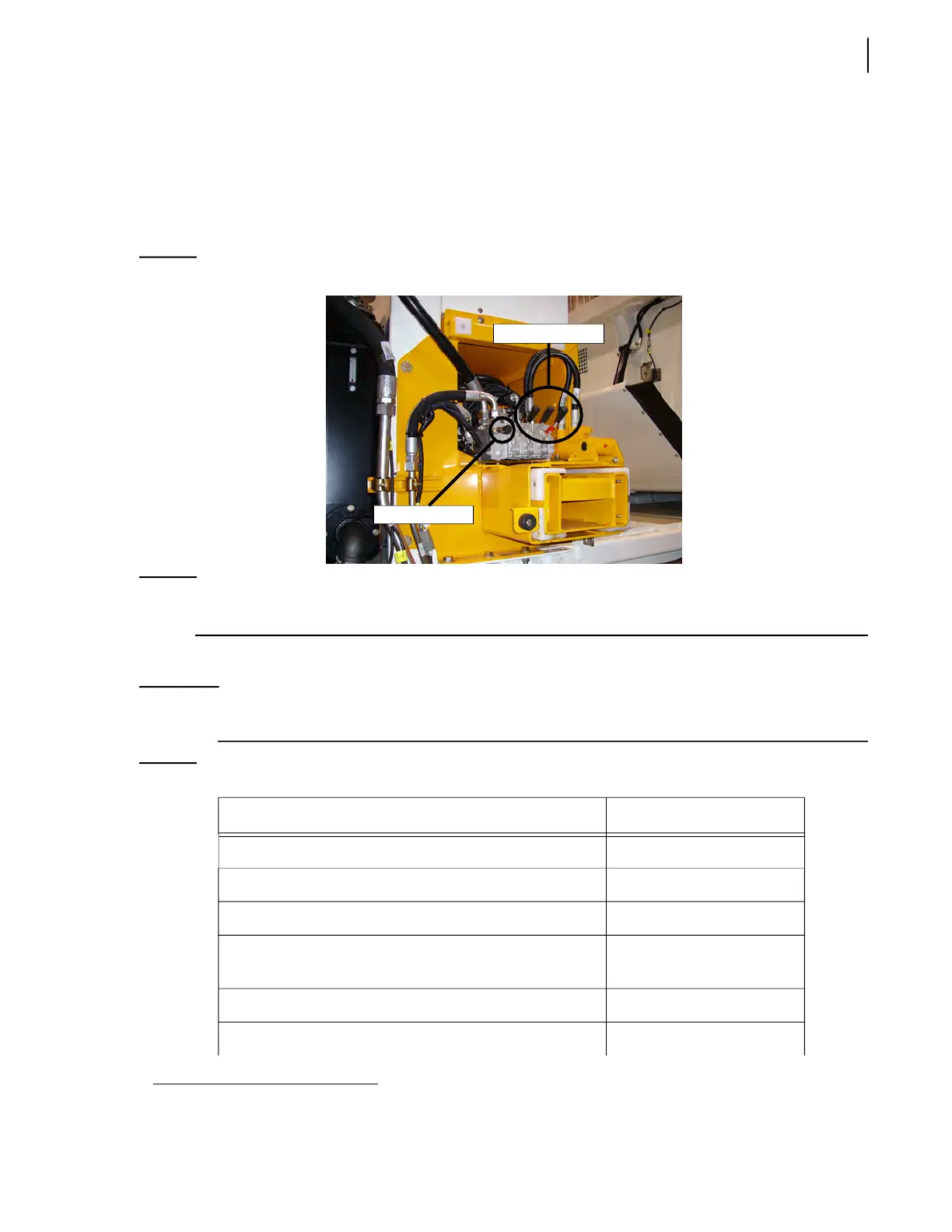
Control levers (see Figure 5-20) are delivered with the vehicle to make pressure adjustments and to
manually operate the arm if necessary.
Figure 5-20
Control levers and quick coupler
NOTE: A helper may be needed when adjusting the arm pressure. Use all necessary safety precautions
around the vehicle at all times.
Refer to Table 1 to correctly adjust the pressure for each function of the lifting arm.
IMPORTANT: Before performing the following procedure, make sure that all function levers and their adjustment
screws have been properly identified on the valve (see Figure 5-4).
1. Except for the gripper section of the valve which does not modulate the hydraulic flow into the gripper cylinder.
Table 1 Hydraulic pressure table (cont’d)
Function Pressure setting
Danfoss PVG-32 main relief valve 2000 ± 50 PSI
Gripper close 1200 ± 50 PSI
Gripper open 1200 ± 50 PSI
Gripper cylinder holding valve (to keep it open), if
equipped
650 ± 50 PSI
Arm up System pressure
Arm down System pressure
Control levers
Quick coupler
 Loading...