200 Lifting Arm
Use the adjustment screw on the curb side for the end-of-stroke lowering motion (See A in
Figure 10-14); use the adjustment screw on the street side for the end-of-stroke raising motion
(See B in Figure 10-14).
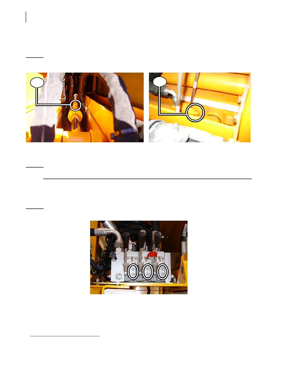
Figure 10-14
Cushion adjustment screws - Up/Down cylinder (curb side: A; street side: B)
Adjusting Arm Speed
NOTE: No arm speed adjustment is required unless when replacing the valve or one of its sections.
Arm speed is controlled by the amount of hydraulic fluid (flow) that is being sent to the arm cylinder.
The arm control valve spools can limit the flow of hydraulic oil, depending on the section of the
valve
1
. Flow is limited by two movement restrictors located on each section.
Figure 10-15
Movement restrictors
The arm movements, extension/retraction and tilt, are preset in factory to the maximum speed. The
gripper speed (opening and closing) has also been set in factory to its optimal value in order to allow
smoother grabbing of the cart.
1. Limiting spool strokes limits the quantity of oil (flow) going through them. Controlling the flow of oil means controlling arm speed.
A
B
 Loading...