Lifting Arm 197
6. Loose the locknut.
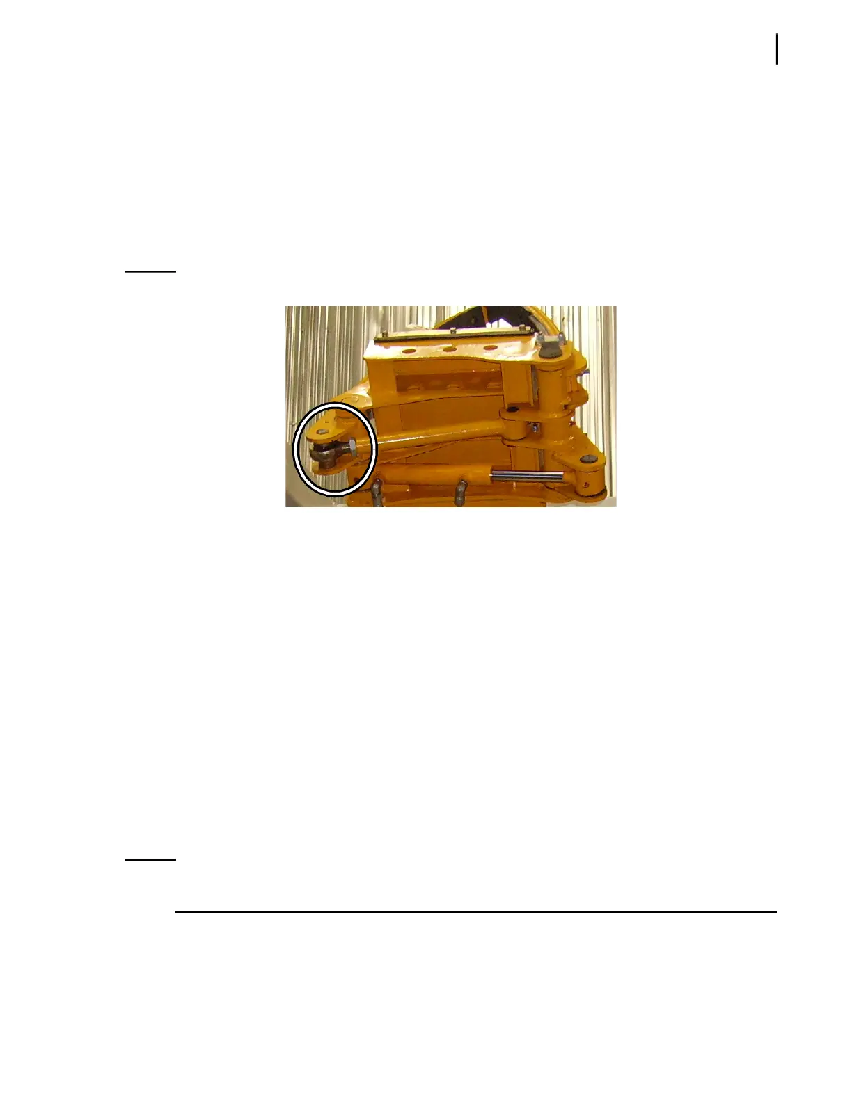
7. Turn the swivel eye clockwise or counterclockwise to adjust the rod length.
8. When the correct length is achieved, tighten the locknut.
9. Replace the adjustment rod into position.
10. Put back the pin.
11. Test the operation.
12. Repeat the procedure if required.
Figure 10-11
Adjusting gripper adjustment rod
Bleeding Air Out of the Lifting Arm Hydraulic
Circuit
After opening the HELPING-HAND™ hydraulic circuit to replace (for example) a cylinder or a valve, air
might enter into the hoses located between the arm control valve and the arm cylinder. As the air
cannot be completely removed by the normal use of the arm, the system must be bled.
The H
ELPING-HAND™ is composed of three hydraulic subcircuits, two of which must be bled
individually depending on the modifications done. Those subcircuits are the following:
Gripper hydraulic circuit
This subcircuit, which includes one cylinder (bore 1 1/2 in., stroke between 5 and 7 in.) and a valve,
controls the open/close motion of the gripper in order to grip containers.
In/Out hydraulic circuit
This subcircuit, which includes one cylinder (bore 1 1/2 in., stroke 54 in.) and a valve, controls the
extend/retract motion of the arm in order to reach containers and come back close to the truck for
travelling.
NOTE: The Up/Down hydraulic circuit needs not to be bled because air that may be inside the circuit
can easily be removed by the normal use of the arm.
To bleed the gripper circuit:
1. Apply all safety measures to ensure safety around the vehicle at all times and make sure to have
enough room to fully operate the arm and the gripper.
 Loading...