10
Drain line must be insulated with a closed cell
insulation. Insulation must cover the entire length of
thedrainhose,includingttings.Thedrainshouldbe
installed in such a manner that water does not collect
in sags or other low points, as condensation will form.
! CAUTION
Pouring hot water into drain may cause the Drain Tube
tocollapse.Allowonlylukewarmorcoldwatertoenter
Drain Tube. Pouringcoeeteaandsimilarsubstances
into drain may cause the Drain Tube to become
cloggedwithcoeeorteagrounds,orothersolid
particles.
! ATTENTION
Dispenser Installation
1. Remove the cup rest, drip tray, splash plate, merchandiser,
and top cover from the unit.
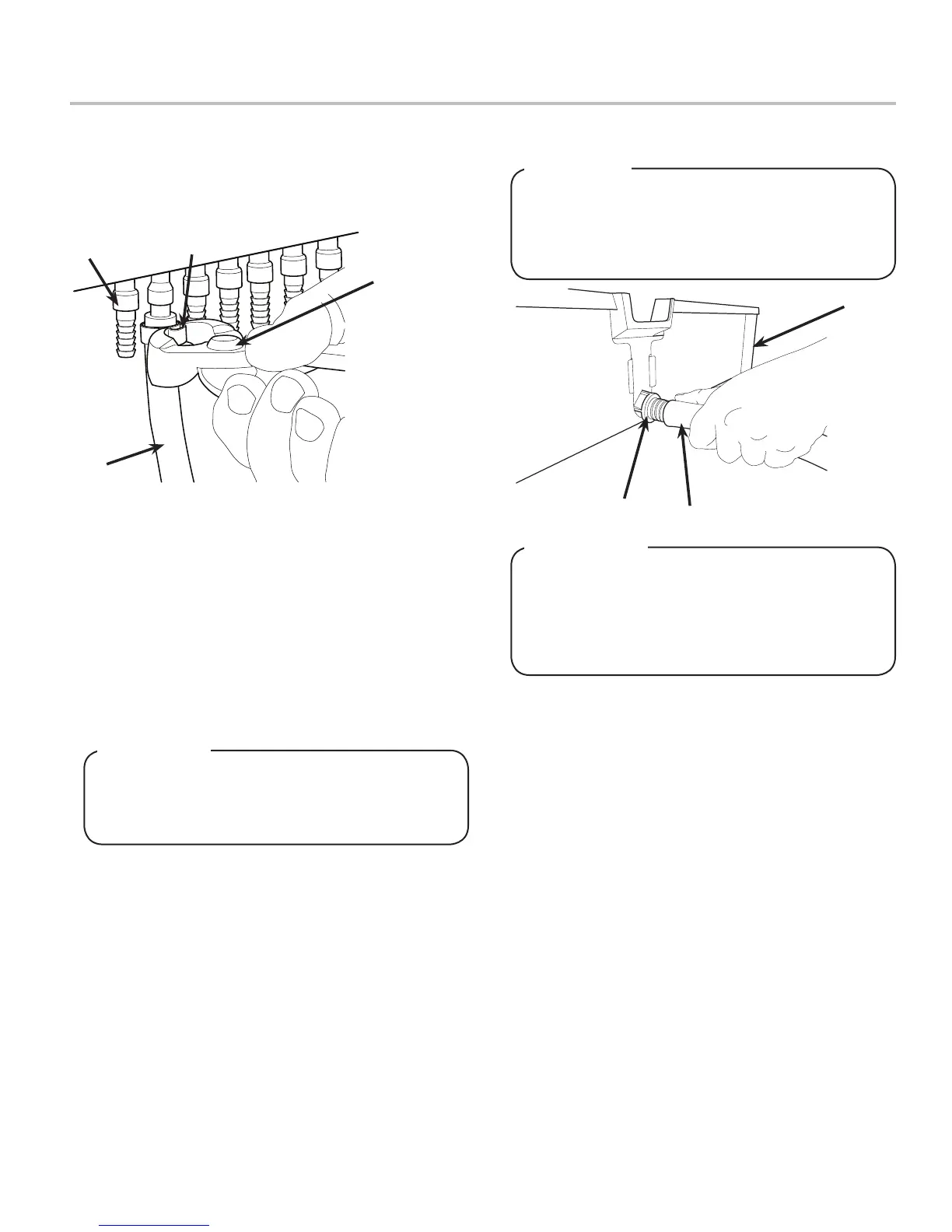
2. Route appropriate tubing from the water source to the plain
water inlet at the front of the unit and connect tubing to inlet
using the oetiker pliers and ttings,(see Plumbing Diagrams
on the front of the unit or on pages 26-27 for reference).
3. Connect tubing to water source then ush water lines to
check for leaks.
4. Route appropriate tubing from the remote carbonator
locaton to the carbonated water inlet at the unit and connect
tubing to inlet.
5. Route appropriate tubing from the syrup pump location to
the syrup inlets and connect tubing to all syrup inlets.
6. Route appropriate tubing from the CO
2
source location to
the CO
2
inlet at the remote carbonator location.
7. Install remote carbonator per manufacturer’s instructions.
8. Route the power supply cord to a grounded electrical outlet
of the proper voltage and amperage rating.
DO NOT PLUG UNIT INTO GROUNDED ELECTRICAL
OUTLET AT THIS TIME. Makesurethatallwaterlines
aretightandunitisdrybeforemakinganyelectrical
connections
! WARNING
9. Route drain hose from designated open type drain to tting
on Drip Tray and connect hose to tting.
10. Reattach Drip Tray/Cup Rest to unit.
A
B
C
A. Oetiker Pliers
B. Fitting
C. Tubing
D. Syrup/Water
Inlet
D
A
A. Drain Fitting
B. Drain Line
C. Drip Tray
B
C