8
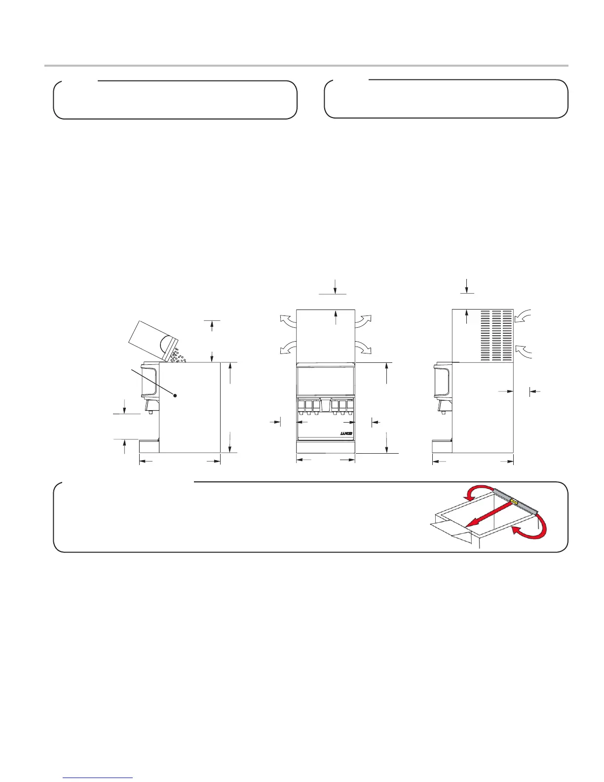
Selecting/Preparing a Counter Location
1. Select a level, well ventilated location that is in close
proximity to a properly grounded electrical outlet, within ve
(5) feet (1.5 m) of a drain, a water supply that meets the
requirements shown in the Specications section found on
pages 4-6, away from direct sunlight or overhead lighting,
and has sucient clearance for air circulation.
2. Sucient clearance must be provided, if an ice maker is not
installed, to allow lling ice compartment from a ve gallon
bucket (a minimum of 16 inches is recommended).
3. The selected location should be able to support the weight
of the dispenser, ice and possibly an icemaker being
installed after counter cut out is made. Total weight (with
icemaker) for this unit could exceed 800 pounds (363.6kg).
Lancer does NOT recommend the use of shaved or
akeiceinthedispenser.
NOTE
4. Unit may be installed directly on countertop or on legs. If
installed directly on the counter, unit must be sealed to the
countertop with an FDA approved sealant. If an icemaker is
to be mounted on top of dispenser, do not install dispenser
on legs.
5. Select a location for the remote pump deck, syrup pumps,
CO
2
t a n k , s y r u p c o n t a i n e r s , a n d w a t e r l t e r ( r e c o m m e n d e d ) .
Please see General System Overview on page 5 for
reference.
6. U s i n g C o u n t e r C u t o u t T e m p l a t e p r o v i d e d , c u t o u t r e q u i r e d
opening for the water, syrup, and CO
2
lines in the
designated dispenser location.
PUSH
I C E
AIR
OUT
AIR
OUT
AIR
OUT
AIR
OUT
MINIMUM of 6" (152 mm)
AIR
IN
AIR
IN
ecnaraelc )mm 251( "6
ecnaraelc )mm 251( "6
22" (559 mm)
MUMINIM of 6" (152 mm)
34" (864 mm)
30 1/2" (775 mm)
clearance above ice maker
MINIMUM of 6" (152 mm)
clearance above ice maker
ecnaraelc llaw
SUFFICIENT CLEARANCE FOR
FILLING MANUALLY WITH ICE,
WHEN ICE MAKER NOT USED
9 3/4” (248 MM)
DISPENSE HEIGHT
ENSURE KEY SWITCH
IS ACCESSIBLE
36” (925 MM)
In order to facilitate proper dispenser drainage, ensure that the dispenser is level,
fronttobackandsidetoside.Placealevelonthetopoftherearedgeofthe
dispenser. The bubble must settle between the level lines. Repeat this procedure
for the remaining three sides. Level unit if necessary. For optimum performance
place the unit at a 0° tilt. The maximum tilt is 5°.
Leveling the Dispenser:
The dispenser should only be installed in a location
where it can be overseen by trained personnel
NOTE