LAUNCH PAD V
User's Manual
63
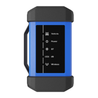
1. RUN LED -
if the GREEN LED is steady ON, it indicates the clips are well
connected. If it keeps blinking, it indicates that the clips have poor contact.
2. POWER LED -
illuminates RED if the battery tester has been powered up.
3. Data I/O Port -
connects the battery tester to the diagnostic tool via data
cable so that the signal can be displayed on the tool.
4. Handle
5. Battery Connector -
connects the battery clamps battery to the
vehicle’s battery for battery test.
Technical Parameters
Working voltage 9
~
18V DC
Average working current
<
100mA
Working temperature -20
℃
- 50
℃
Storage temperature -30
℃
- 70
℃
7.2.1.3 Accessory Checklist
Battery Clamps Cable
(For connecting the battery test and the vehicle's battery)
Data Cable
(For connecting the battery tester and the diagnostic tool.)
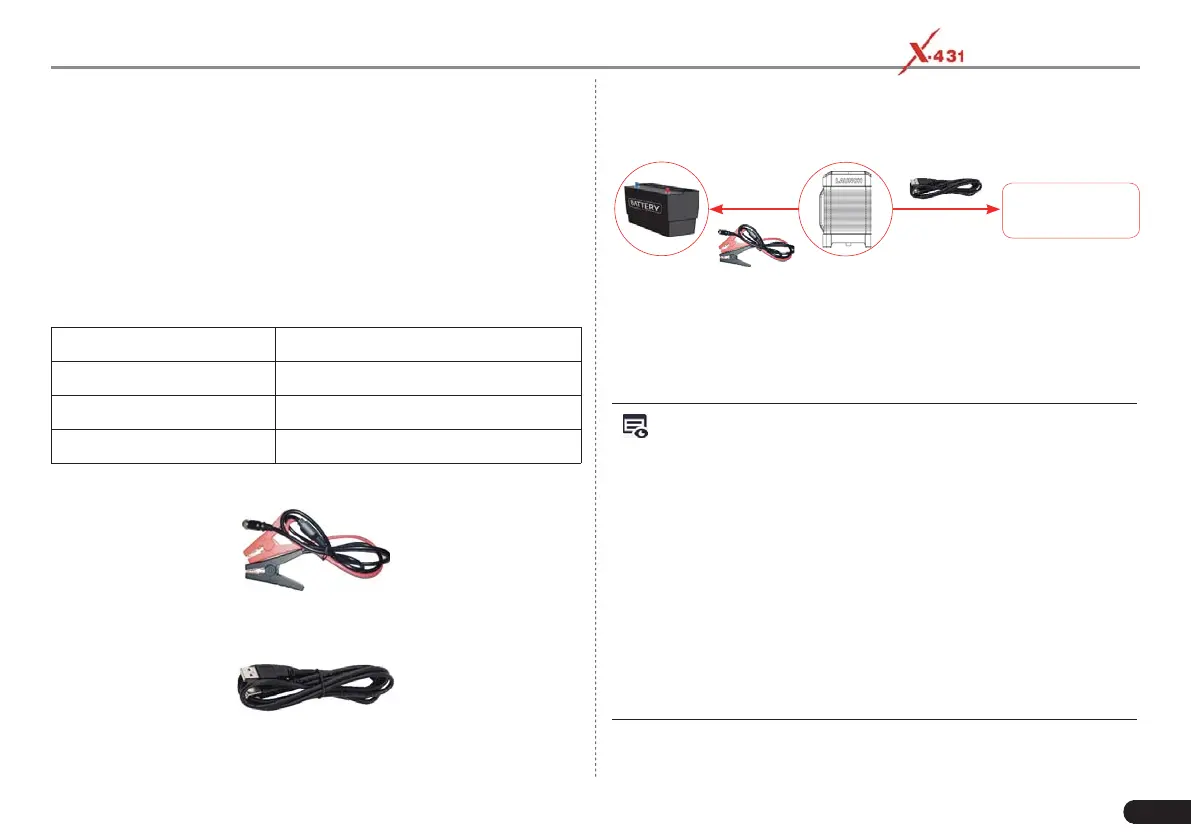
7.2.1.4 Connections
Launch-specifi c
diagnostic tool
Battery tester
Vehicle battery
1. Connect one end of the data cable to the Data I/O port of the battery
tester and the other end to the data I/O port of the diagnostic tool.
2. Before testing,
connect one end of the battery clamps cable to the
battery tester and the other end to vehicle’s battery.
First: RED
to
Positive (
+) and then
BLACK
to Negative (-).
Notes:
1. Wait about 10s and begin to communicate since the battery
tester needs to initialize after connection is complete, otherwise,
communication may fail.
2. Do not perform any test until the clips and data cable are properly
connected.
To get more accurate test results, the clips must be
connected to the positive and nagative poles, NOT on the screws.
3. Pay more attention to connect the clip. The battery poles connect with
conductor, which makes the clip has a poor connection when testing
battery. A tolerance of dozens of CCA may occur if the clip is out of
position, or oil, dust attaches on the pole. The gear and main body of
clip should be fully matched with battery poles.
4.
After test, plese remove the BLACK clip first and
then the RED one.