50
LAUNCH PAD V
User's Manual
7.1.2 Components and Accessories
7.1.2.1 Components & controls
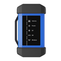
Sensorbox
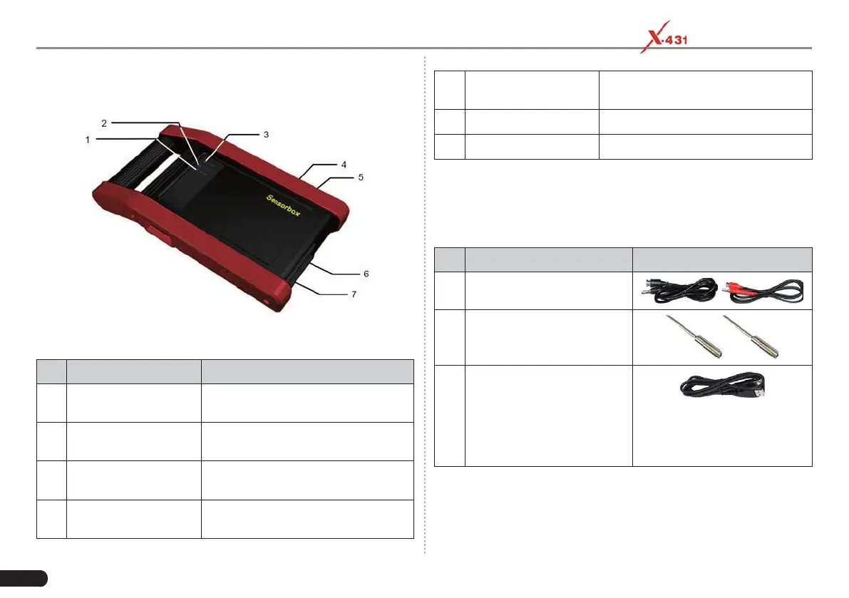
Below shows the ports and indicators for the Sensorbox
No. Name Description
1
Data receiving LED
Indicator (green) for receiving data
from the diagnostic tool.
2
Data sending LED
Indicator (green) for sending data to
the diagnostic tool.
3
Power LED
It keeps steady on (red) after
theSensorbox is powered on.
4
B-shaped data I/O port
Connect to the diagnostic tool with
data cable.
5
Power Interface
Connect to power supply through the
power adaptor.
6
COM Common terminal of multimeter
7
VΩHz Testing terminal of multimeter
7.1.2.2 Accessories
The Sensorbox accessories include sensor test cable, probe etc. For
detailed items, please see the packing list.
Below formulates the Sensorbox accessories:
No. Name Picture
1
Sensor test cable
2 Sensor probes
3
Data Cable
Connects the Sensorbox and
diagnostic tool so that the
sampled signal can be displayed
on the diagnosƟ c tool.