Doc No. FM0410 issue N Page 37
FIT LK1, LK2 & LK3 ALL IN POSITION 'A'
WHEN A DOOR ENTRY TELEPHONE
IS CONNECTED
SET
BINARY
ADDRESS
1
SET OPTIONS DIL SW2
ON WHEN A DOOR ENTRY
TELEPHONE IS CONNECTED
2 34 56 78
ON
1 23 45 67 8
ON
LK2
(ALL OTHERS OFF)
LK3
LK1
26. DOOR ENTRY TELEPHONE INSTALLATION
dual handset enable output
10V DC supply & strobe +ve
Note, the Advent xt controller must be reset for it to detect a telephone handset has been connected.
DUAL HANDSETS
Normally only one telephone will be connected per channel, if a flat requires a second handset then both telephones
should be ZFT221 Dual Handset models. Alternatively, dual handset interface boards (P/No. A00438) must be fitted in
both ZFT220 telephones. The second handset MUST have link LK3 moved to position “B” (slave) - it is not possible to have
more than 2 telephones per flat. For connection details see Tynetec Drg No. ZXT100 sheet 4.
Note: the RESET button on the Advent xt controller must be pressed for it to detect a second handset has been connected.
OPTIONAL HARD OF HEARING STROBE
A hard of hearing strobe light (P/No. ZSL047) can be connected across the telephone
“STROBE” (-ve) and 10V (strobe +ve) terminals.
Note; a maximum of 2 strobes per flat is permitted.
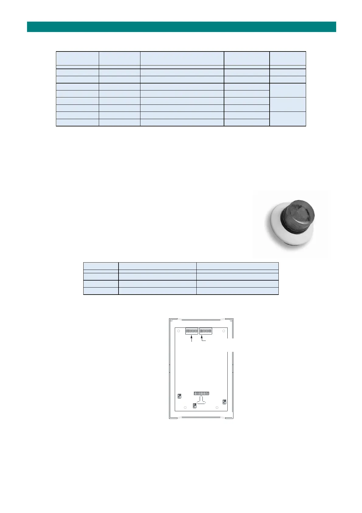
TELEPHONE LINK SETTINGS
Links LK1 & LK2 should always be set in the “SDATA” & “SCLK” positions on Advent xt systems.
Link LK3 must be in position “A” (master) when only one telephone is fitted per flat.
INTERCOM DIL SW & LINK SETTINGS
When a door entry telephone is connected to an
intercom make the following settings;
Set the “Options” DIL switch number 2 “ON”
Set Links LK1/LK2/LK3 in position “A”
Note: the clean contact relay output is not
available when a telephone is connected.
PROGRAMMING
The Speech Time, Lock Release Time, Privacy Time, No. of Ring Cycles and Door Open LED must all be set/enabled in the
“Door Entry Setup” programming - see the Advent xt Programming Manual (Tynetec Doc No. FM0411).