29
6. Assembly
Ergomodule
For raising the eye level of the tube opening, the
30 mm or 60 ergomodule mm may be used.
It is fastened in place with the side clamping
screw.
Ergolift
A base for the stand featuring adjuster wheels
for the base’s height and angle is available to
ensure an optimal working position.
Calculation of the magnification on the monitor
The magnification M
TV
on the monitor can be
calculated with the following formula or
measured with a stage micrometer and a cm
scale:
M
TV
= Objective magnification x
factor of magnification changer*x
TV adapter magnification x
monitor diameter
chip diameter of camera
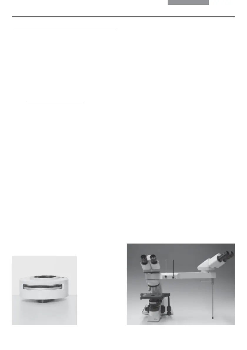
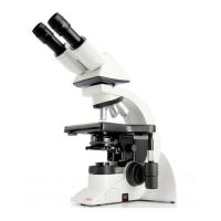
Fig. 29 Viewing attachment (here with Leica DM1000)
1 Movement of light pointer in x and y direction,
and switchover of color filter
2 Brightness control
3 Adjustment of arm support
The external power supply (illuminated arrow) is not
illustrated.
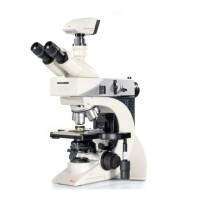
Fig. 28 Magnification changer
Magnification Changer
Optionally, a magnification changer (fig. 28) can
be used, which is manually operated. On the
knurled ring, the following magnification factors
can be set:
1x; 1.5x; 2x
Viewing Attachments
Viewing attachments featuring illuminated
pointers are available for groups of up to 20
viewers.
The support (29.3) must be aligned precisely.
The fade-in arrow can be moved in x and y
direction (move the lever vertically or pull out/
push in) (21.1) If this lever is rotated, the color of
the arrow can be changed (red/yellow). Use the
brightness control (29.2) to adjust the brightness
of the arrow.
12
3