Appendix B. Component reference
When installing optional components, you will often need to remove other components to gain access.
Internal connector locations and procedures for removing and installing components to gain access to other
system components are in this appendix.
• “Internal connectors” on page 103
• “Component access” on page 110
Internal connectors
The topics in this section provide information about connectors that are inside the server.
For information about external connectors on the front and rear of the server, see “Front view” on page 16
and “Rear view” on page 21.
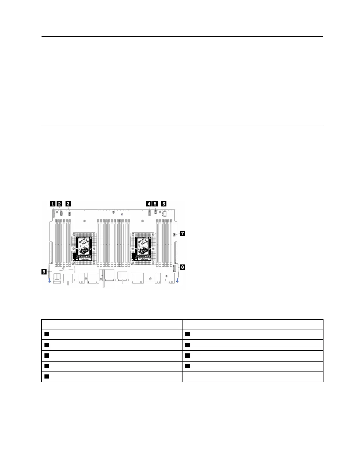
System-board connectors
The following illustration shows the internal connectors on the system board.
Figure 47. System-board connectors
Table 22. System-board internal connectors
Callout Callout
1 “Front panel” connector 6 Hard disk drive “Power” connector
2 “Fan board” power connector (J56) 7 Front panel “USB” connector
3 “Fan board” signal connector (J40) 8 “PCIe/NVMe” connector
4 “Front video” connector 9 “NVMe” connector
5 Hard disk drive “Signal” connector
Storage-board-assembly connectors
The following illustration shows the internal connectors on the storage board assembly.
© Copyright Lenovo 2017 103

 Loading...


