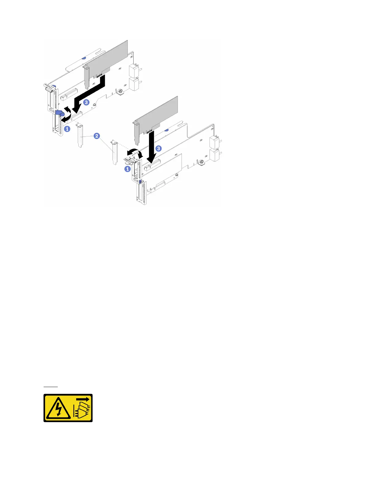
Figure 68. Adapter installation (slots 16 and 17)
Step 1. Open the retention latch.
Step 2. Align the adapter with the riser slot and insert it; then, press the adapter into the riser until the
connector is fully seated.
Step 3. Close and lock the retention latch.
If you have no other operations to perform on the riser after installing an adapter in slots 1 through 4:
1. If any of the adapters in the riser have internal cables, make sure that they are connected before
installing the riser in the I/O tray.
2. Install the riser in the I/O tray. See “Install the riser for slots 16 and 17” on page 180.
3. Install the I/O tray in the chassis and connect all cables. See “Install the I/O tray” on page 153.
Compute tray (upper or lower) replacement
Use the following procedures to remove and install the upper or lower compute tray.
Remove a compute tray
The upper and lower compute trays are accessed from the front of the server. Open the release levers to
extract the compute tray, pressing the release tabs when it stops to remove the tray fully from the chassis.
S002
CAUTION:
Appendix B. Component reference 123

 Loading...


