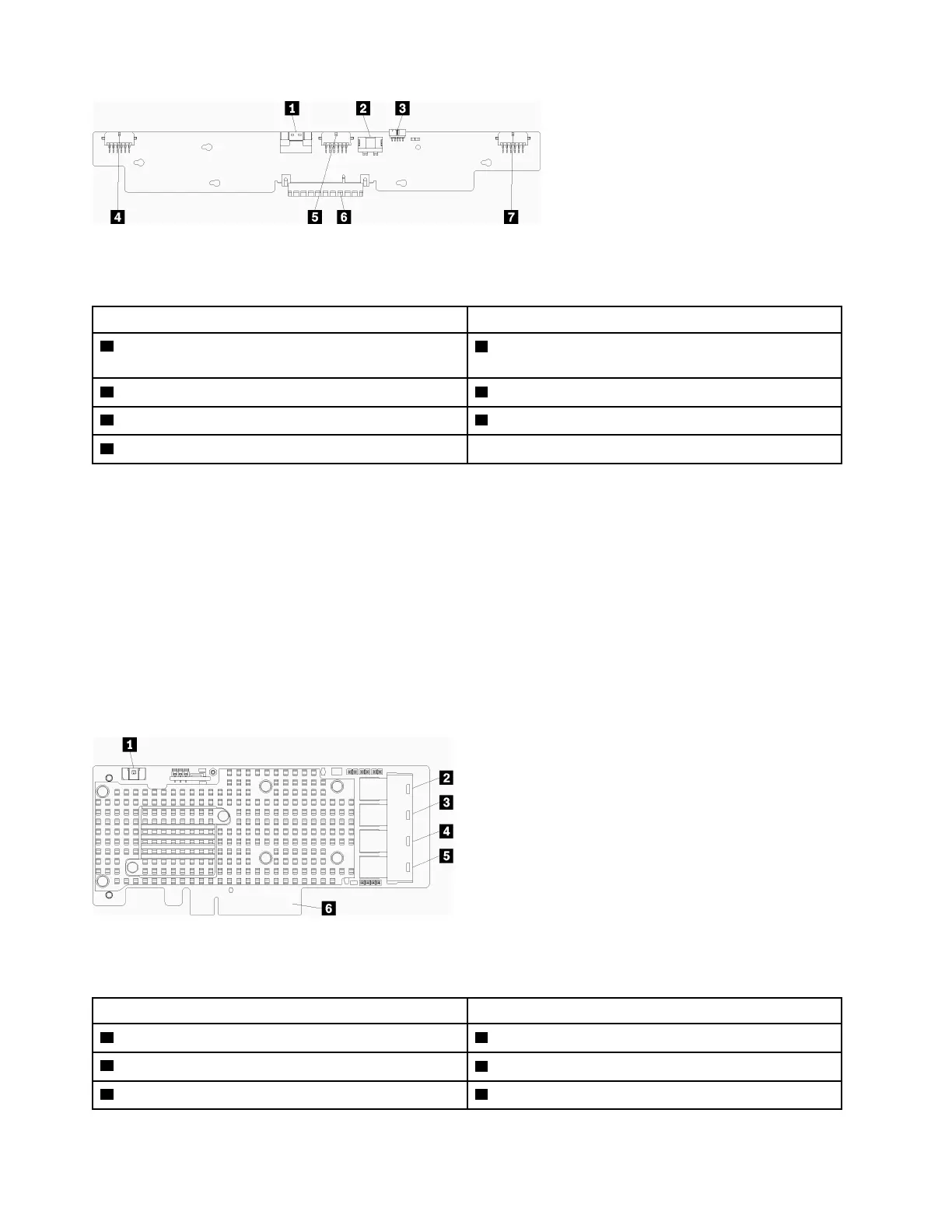
Figure 54. Storage interposer connectors
Table 29. Storage interposer connectors
Callout Callout
1 PCIe SAS interface from system board (PCIE) (SAS
only)
5 Power for drive to backplane 2 or 5 (BP 2/5)
2 Drive power from system board (POWER) 6 PCI connector to RAID card
3 Drive signal from system board (SIDEBAND) 7 Power for drive to backplane 3 or 4 (BP 3/4)
4 Power for drive to backplane 1 or 6 (BP 1/6)
RAID card connectors
The following illustration shows the internal connectors on the RAID card.
There are two basic RAID card configurations.
Notes:
• The RAID cards in the illustration might be different than the RAID card in your system. Connector
locations for all RAID cards is similar.
• Some cable connectors have locks or latches that must be disengaged to disconnect the cable.
For information about RAID card cable routing, see “Cable routing for drives” on page 29.
Figure 55. RAID card connectors (type 1)
Table 30. RAID card connectors (type 1)
Callout Callout
1 RAID flash power module (J14) connector 4 RAID connector for drive backplane 2 or 5 (SAS only)
2 Unused
5 RAID connector for drive backplane 1 or 4 (SAS only)
3 RAID connector for drive backplane 3 or 6 (SAS only) 6 PCI connector to storage interposer
108 ThinkSystem SR950 Setup Guide

 Loading...


