CAUTION:
Make sure that all server power cords are disconnected from their power sources before performing
this procedure.
Install the M.2 drives before you install the M.2 backplane. See “Install an M.2 drive” on page 72.
Before you install an M.2 backplane option:
1. If the I/O tray is installed in the server, remove it. See “Remove the I/O tray” on page 152.
2. If the riser for slots 10 through 15 (right riser) and the riser for slots 16 and 17 are installed, remove one of
them to access the M.2 backplane connector. See “Remove the riser for slots 10 through 15 (right riser)”
on page 171 or “Remove the riser for slots 16 and 17” on page 174.
Complete the following steps to install the M.2 backplane.
Watch the procedure. A video of the installation process is available:
• Youtube:
https://www.youtube.com/playlist?list=PLYV5R7hVcs-DbSYJFY74PoKmph7vgrkKH&playnext=1
• Youku: http://list.youku.com/albumlist/show/id_50952215
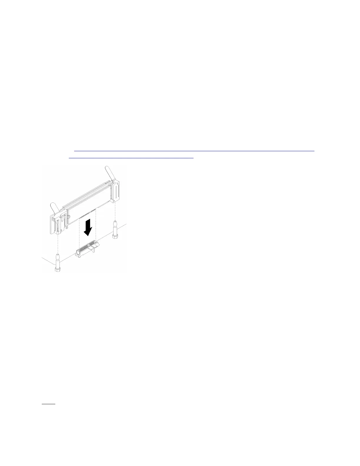
Figure 45. M.2 backplane installation
Step 1. Align the openings in the plastic supports at each end of the M.2 backplane with the guide pins on
the system board; then, insert the backplane in the system-board connector.
Step 2. Press down on the M.2 backplane to fully seat it.
After installing the M.2 backplane option:
1. If you removed a riser and have no adapters to install in it, install the riser. See “Install the riser for slots
10 through 15 (right riser)” on page 177 or “Install the riser for slots 16 and 17” on page 180.
2. If you have no additional options to install in the I/O tray, install it. See “Install the I/O tray” on page 153.
Install a power supply
Insert the power supply in its bay and press it in until the release tab locks. Power supplies are hot-swap
devices that can be installed while the server is powered on.
S001
Chapter 3. Server hardware setup 81

 Loading...


