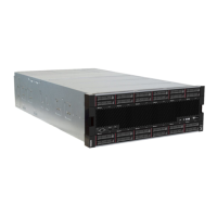
Figure 23. Front cover removal
Step 1. Press release buttons at either side of the front cover.
Step 2. Pull the cover forward and remove it from the server.
Install the compute system board
Compute system boards are in the upper or lower compute tray that is accessed from the front of the server.
S002
CAUTION:
The power control button on the device and the power switch on the power supply do not turn off the
electrical current that is supplied to the device. The device also might have more than one power
cord. To remove all electrical current from the device, ensure that all power cords are disconnected
from the power source.
CAUTION:
Make sure that all server power cords are disconnected from their power sources before performing
this procedure.
Notes:
• If you are installing an optional processor or memory module, perform those tasks first. See “Install a
processor-heat-sink module” on page 51 or “Install a memory module” on page 54.
• Make sure that memory module fillers are installed in all vacant memory module connectors.
• Make sure that all memory air baffles are installed. See “Memory air baffle replacement” on page 161.
Chapter 3. Server hardware setup 49

 Loading...


