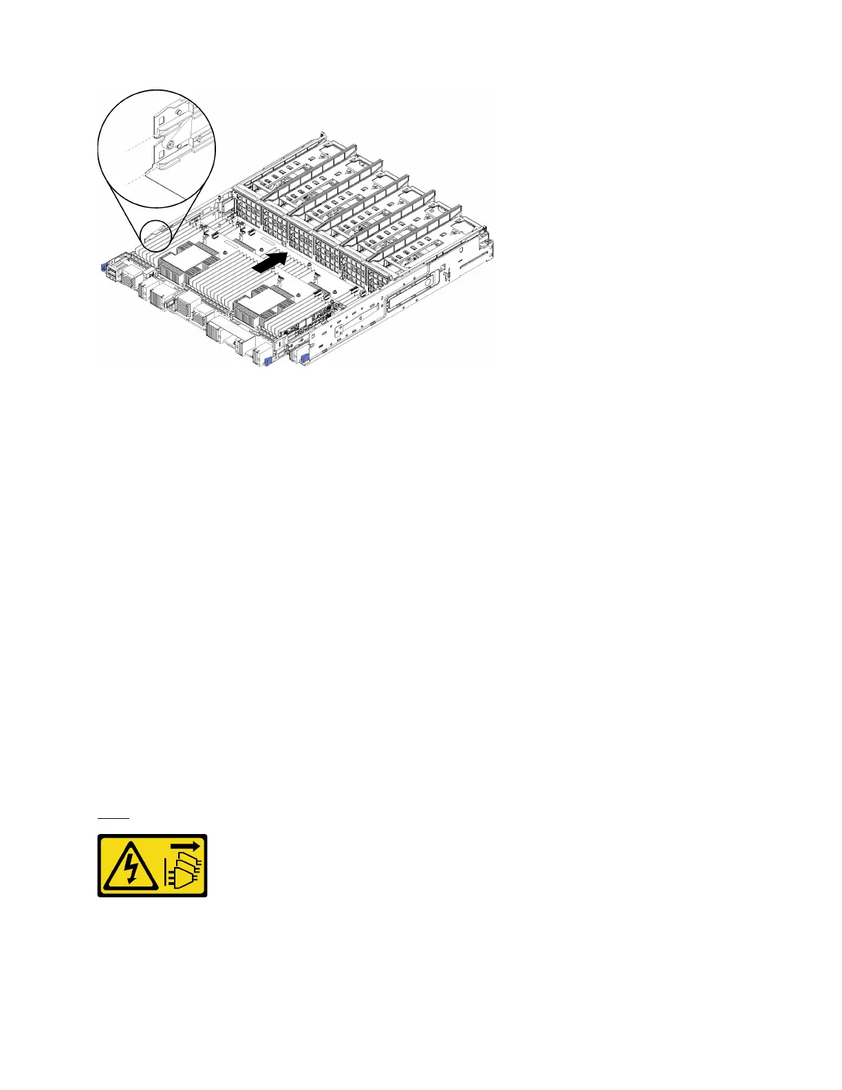
Figure 73. Compute system board installation
Step 1. Align the compute system board with the rails in the compute tray; then, insert the compute system
board, making sure that the rails on the board fit into the slots in the compute tray.
Step 2. Slide the compute system board into the compute tray until the release clips snap into the locked
position.
Step 3. Connect all cables on the compute system board that go to connectors in the compute tray. See
“Internal cable routing” on page 24.
After you install the compute system board:
• If you installed the lower compute system board in a compute tray, slide the upper compute system board
or filler back into the compute tray until the release clips snap into the locked position.
• If you are not installing another compute system board, install the compute tray and front cover. See
“Install the compute tray (fully removed)” on page 125 and “Install the front cover” on page 139.
Compute system board filler replacement
Compute system board fillers are in the upper or lower compute tray that is accessed from the front of the
server.
Remove a compute system board filler
Remove a compute system board filler by pressing the release clips on the filler, and sliding it out of the
compute tray.
S002
CAUTION:
The power control button on the device and the power switch on the power supply do not turn off the
electrical current that is supplied to the device. The device also might have more than one power
cord. To remove all electrical current from the device, ensure that all power cords are disconnected
from the power source.
Appendix B. Component reference 129

 Loading...


