• 2 Network activity LED: When this LED flickers, it indicates that the server is transmitting to or receiving
signals from the Ethernet LAN.
•
3 System ID button/LED: Use this blue LED to visually locate the server among other servers. This LED
is also used as a presence detection button. You can use Lenovo XClarity Administrator to light this LED
remotely.
•
4 System-error LED: When this yellow LED is lit, it indicates that a system error has occurred. A system-
error LED is also on the rear of the server. Messages on the LCD system information display panel and
LEDs on other server components might also be lit to help isolate the error. This LED is controlled by the
Lenovo XClarity Controller.
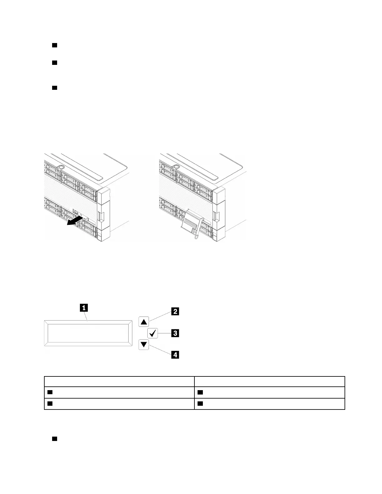
LCD system information display panel
The front operator panel comes with a tab, which can be pulled to access the LCD system information
display panel. See “LCD system information display panel” on page 19 for more information.
LCD system information display panel
The following section includes an overview of the LCD system information display panel, which displays
various types of information about the server.
The LCD system information display panel attached to the front of the server allows quick access to system
status, firmware, network, and health information.
Table 5. LCD system information display panel
Callout Callout
1 Information display panel
3 Select button
2 Scroll up button 4 Scroll down button
Note: Press the scroll-up and scroll-down buttons at the same time to refresh the LCD system information
display panel.
•
2 Scroll up button: Press this button to scroll up or scroll to the left in the main menu to locate and select
the system information that you want displayed.
Chapter 2. Server components 19

 Loading...


