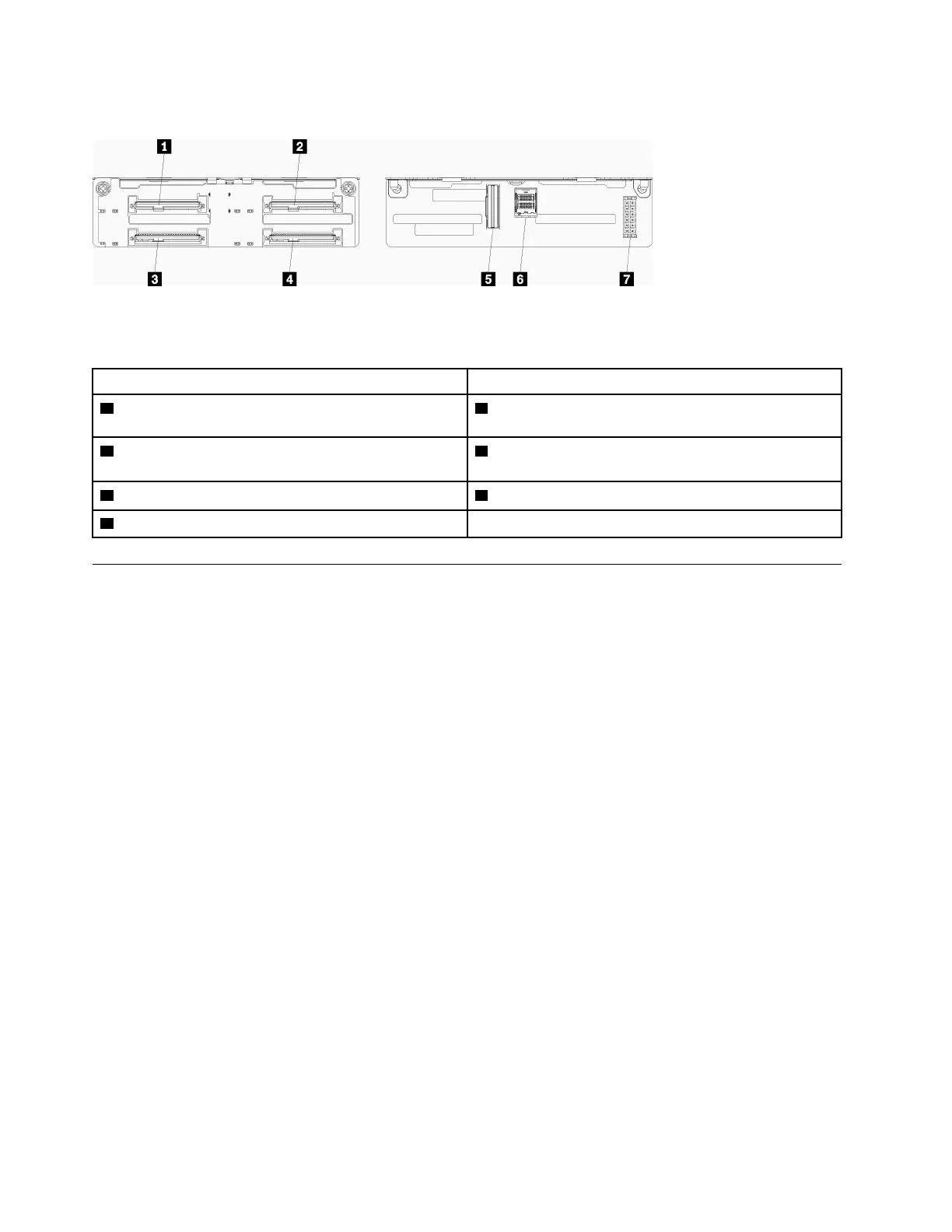
SAS/NVMe drive backplane connectors
Figure 58. SAS/NVMe drive backplane connectors
Table 33. SAS/NVMe drive backplane connectors
Callout Callout
1 Drive connector for SAS or NVMe drives 0, 4, 8, 12, 16,
and 20
5 NVMe signal from compute board or storage tray
2 Drive connector for SAS or NVMe drives 2, 6, 10, 14,
18, and 22
6 SAS signal from RAID card
3 Drive connector for SAS drives 1, 5, 9, 13, 17, and 21
7 Backplane power from interposer
4 Drive connector for SAS drives 3, 7, 11, 15, 19, and 23
Component access
When installing optional components, you will often need to remove other components to gain access.
Procedures for removing and installing components to gain access to other system components are in this
section.
Adapter replacement
Adapters are in several locations in the I/O tray that is accessed from the rear of the server. You can install up
to 17 adapters in the server. The removal and installation procedures for each riser type are different and are
described in the following topics:
• PCIe adapters 1 through 4: see “Remove a PCIe adapter from slots 1 through 4” on page 110 and “Install
a PCIe adapter in slots 1 through 4” on page 117
• PCIe adapters 5 through 8 and the LOM adapter (slot 9):
– For PCIe adapters 5 through 8, see “Remove an adapter from slots 5 through 8” on page 112 and
“Install an adapter in slots 5 through 8” on page 118
– For the LOM adapter (slot 9), see “Remove a LOM adapter from slot 9” on page 113 and “Install a LOM
adapter in slot 9” on page 119
• PCIe adapters 10 through 15: see “Remove a PCIe adapter from slots 10 through 15” on page 114 and
“Install a PCIe adapter in slots 10 through 15” on page 120
• I/O adapters 16 and 17 (riser card): see “Remove an I/O adapter from slots 16 and 17” on page 115 and
“Install an I/O adapter in slots 16 and 17” on page 122
Remove a PCIe adapter from slots 1 through 4
PCIe adapters in slots 1 through 4 are in an I/O tray riser that is accessed from the rear of the server. After
removing the I/O tray and the riser for slots 1 through 4 (left riser), open the retention latch and remove the
adapter from the riser.
110
ThinkSystem SR950 Setup Guide

 Loading...


