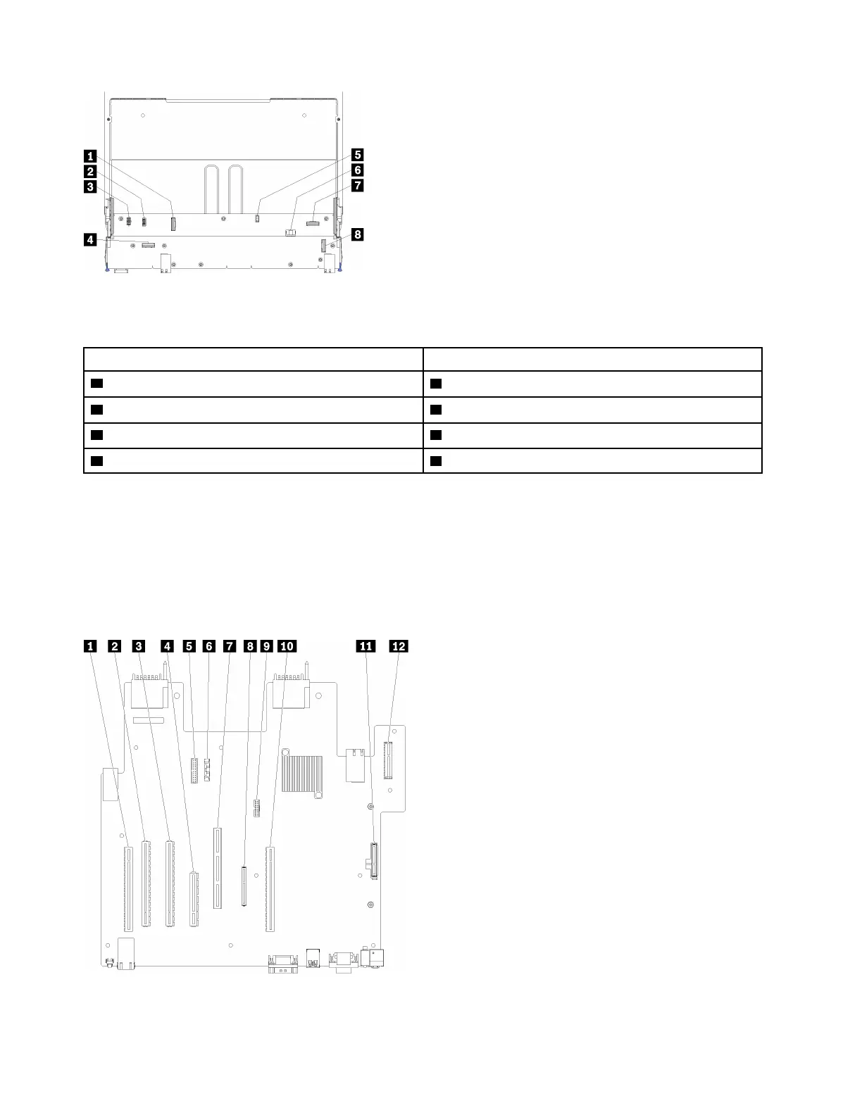
Figure 48. Storage-board-assembly connectors
Table 23. Storage-board-assembly connectors
Callout Callout
1 “NVMe” connector
5 Hard disk signal connector (J13)
2 Fan signal connector (J5) 6 Hard disk drive power connector (J2)
3 Fan power connector (J3) 7 “PCIe” connector
4 “NVMe” connector 8 “NVMe” connector
I/O-tray connectors
The following illustration shows the internal connectors on the I/O-tray (includes connectors for slots 5
through 8 and the LOM connector for slot 9).
For information about connectors on I/O-tray risers, see “I/O-tray riser connectors” on page 105. For
information about all external connectors on the rear of the server, including those on the I/O tray, see “Rear
view” on page 21.
Figure 49. I/O-tray connectors
104 ThinkSystem SR950 Setup Guide

 Loading...


