Table 11. Cable routing, common cables (lower tray) (continued)
Cable
Routing
3 Control panel cable
• From: Control panel connector
• To: Lower compute system board in lower compute tray, “Front panel” connector
(see “System-board connectors” on page 103)
Attention: Make sure the operator panel cable is folded beneath the connector, as
shown in Figure 10 “Cable routing, common cables (lower tray)” on page 27 to prevent
the cable from pinching when the compute tray is fully assembled.
4 Fan cage cable
• From: Fan cage connector (underside of fan cage)
• To: Lower compute system board in lower compute tray, “Fan board” power (J56)
and signal (J40) connectors (see “System-board connectors” on page 103)
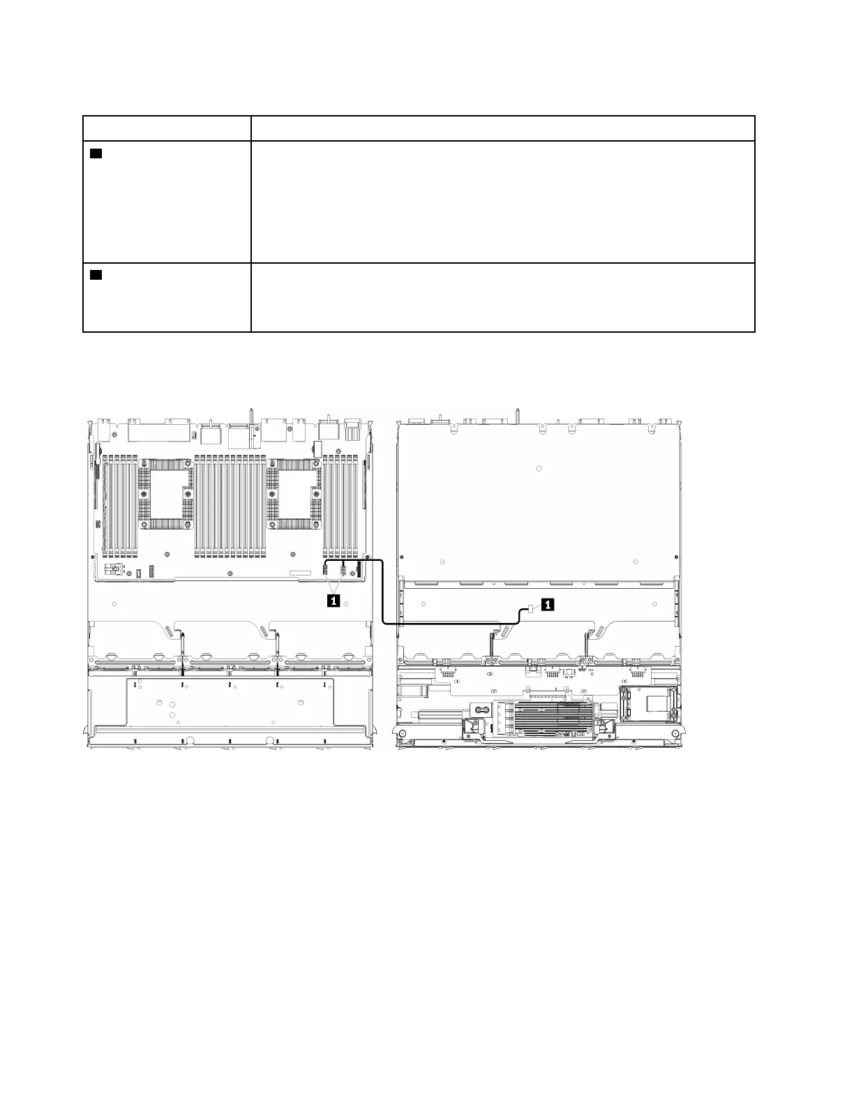
Common cable routing (upper tray)
The following illustration shows cable routing for common components in the upper tray.
Note: In this illustration, the image on the left shows the tray right-side up and the image on the right shows
the tray upside down.
Figure 11. Cable routing, common cables (upper tray with compute system board)
28 ThinkSystem SR950 Setup Guide

 Loading...


