Step1.Installthefixedpowersupply.
a.Positionthepowersupplyonthechassis.
b.Pushthepowersupplytowardtherearoftheserveruntilthepowersupplyengagesthe
chassis.
c.Installthescrewstosecurethepowersupplytothechassis.
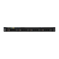
Figure66.Fixedpowersupplyinstallation
Step2.Connecttheinternalpower-supplycablesfromthepowersupplytothepowersupplyconnector
andCPUpowerconnectoronthesystemboard.Tolocatethepowerconnectorsonthesystem
board,see“System-boardconnectors”onpage21.
Step3.Routetheinternalpower-supplycables,securingthemwiththeretentionclips.
Step4.Testthepowersupply:
a.Connectoneendoftheacpowercordforthenewpowersupplyintothepowersupply
connector,andconnecttheotherendofthepowercordintoaproperlygroundedelectrical
outlet.MakesurethatthestandbypowerLEDonthesystemboardislit.See“System-board
LEDs”onpage24.
b.IfthestandbypowerLEDisnotlit,discontinuethisprocedureandobtainanewpowersupply.
c.Pressthepower-controlbutton.Makesurethatthepower-onLEDonthefrontoftheserver
islit.
Iftheserverstarts,proceedtothenextstep.Iftheserverdoesnotstart,disconnecttheacpower
cordandcallforservice.
Step5.Turnofftheserveranddisconnecttheacpowercord.
Step6.Completethepartsreplacement.See“Completingthepartsreplacement”onpage172.
Step7.Pressthepower-controlbutton.Makesurethatthepower-onLEDonthefrontoftheserverislit.
Removingahot-swappowersupply
Whenyouremoveapowersupply,observethefollowingprecautions.
Chapter7.Removingandinstallingservercomponents131
 Loading...


