5NMIbutton
6Ethernetconnector1forsystemmanagement
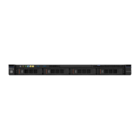
7USBconnectors
8Videoconnector
9acpowerLED(green)10dcpowerLED(green)
11Power-supplyerrorLED(yellow)
1EthernetlinkLED
2EthernetactivityLED
•EthernetlinkLEDs:WhentheseLEDsarelit,theyindicatethatthereisanactivelinkconnectiononthe
10BASE-T,100BASE-TX,or1000BASE-TXinterfacefortheEthernetconnector.
•EthernetactivityLEDs:WhentheseLEDsarelit,theyindicatethatthereisactivitybetweentheserver
andthenetwork.
•acpowerLED
•dcpowerLED
TheseLEDsshowthestatusofthepowersupply.Duringnormaloperation,bothofthemarelitingreen.
Formorepower-supplystatusinformation,see“Power-supplyLEDs”onpage54
.
•Power-supplyerrorLED:WhenthisyellowLEDislit,itindicatesthatthepowersupplyhasfailed.
•Powercordconnector:Connectthepowercordtothisconnector.
•VGAconnector:Connectamonitortothisconnector.
•USBconnectors:ConnectaUSBdevice,suchasaUSBmouse,keyboard,orotherdevicetoanyof
theseconnectors.
•Ethernetconnectors:Useeitheroftheseconnectorstoconnecttheservertoanetwork.Whenyouuse
theEthernet1connector,thenetworkcanbesharedwiththeIMM2throughasinglenetworkcable.
•NMIbutton:Pressthisbuttontoforceanonmaskableinterrupt(NMI)tothemicroprocessor.Bythis
way,youcanbluescreentheserverandtakeamemorydump.Youmighthavetouseapenortheend
ofastraightenedpapercliptopressthebutton.
Note:UsethisbuttononlywhendirectedbytheLenovoservicesupport
•PCIslot1:ThisslotisdedicatedtoServeRAIDM1210SAS/SATAcontroller
•PCIslot2:ThisslotsupportsonePCIExpressGen3x8half-length,full-heightadapter
Operatorinformationpanel
ThefollowingillustrationshowsthecontrolsandLEDsontheoperatorinformationpanel.
Figure8.Operatorinformationpanel
18LenovoSystemx3250M6InstallationandServiceGuide
 Loading...


