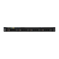
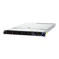
Figure10.Connectorsonthesystemboard
1PCIrisercardconnector
2Microprocessorpowerconnector
3Powersupplyconnector4Backplanepowerconnector
5DIMMslot16DIMMslot2
7DIMMslot38DIMMslot4
9Powerdistributionboardconnector
10Systemfan1connector
11Systemfan2connector12Systemfan3connector
13Systemfan4connector14Mini-SASconnector
15SATAopticaldriveconnector16Operationinformationpanelconnector
17Coin-cellbatteryconnector18FrontUSBconnector
19USBhypervisorkeyconnector20Operatingtemperatureenhancementkitconnector
System-boardswitchesandjumpers
Thistopichelpsyoulocatethejumpersandswitchesonthesystemboardandgetfamiliarwiththeir
functions.
Important:
•Beforeyouchangeanyswitchsettingsormoveanyjumpers,turnofftheserver.Then,disconnectall
powercordsandexternalcables.Reviewtheinformationin“Safety”onpagev,“Beforeremovingor
installingservercomponents”onpage87,and“Turningofftheserver”onpage13.
•Anysystem-boardswitchorjumperblockthatisnotshownintheillustrationsinthisdocumentare
reserved.
•Ifthereisaclearprotectivestickerontheswitchblocks,youmustremoveanddiscardittoaccess
theswitches.
22LenovoSystemx3250M6InstallationandServiceGuide

 Loading...


