Electrical installation
StateLine C control terminals
Analog inputs and outputs
6
l
217
EDS84ASC552 EN 8.1
Example circuit
0 1
"
GND-A
X3
O1U
E84AVSC...
GA A1I
A1U
AR
+10 V /
10 mA
"
U
GND-A
X3
O1U
E84AVSC...
GA A1I
A1U
AR
+10 V /
10 mA
8400SLC012 8400SLC011
2 3
X3
GND-A
O1U
E84AVSC...
GA A1I
A1U
AR
+10 V /
10 mA
int.
24E
GND-IO
GIO
24I
GND-IO
X4
B
"
=
-
+
"
GND-A
X3
O1U
E84AVSC...
GA A1I
A1U
AR
+10 V /
10 mA
8400SLC009 8400SLC013
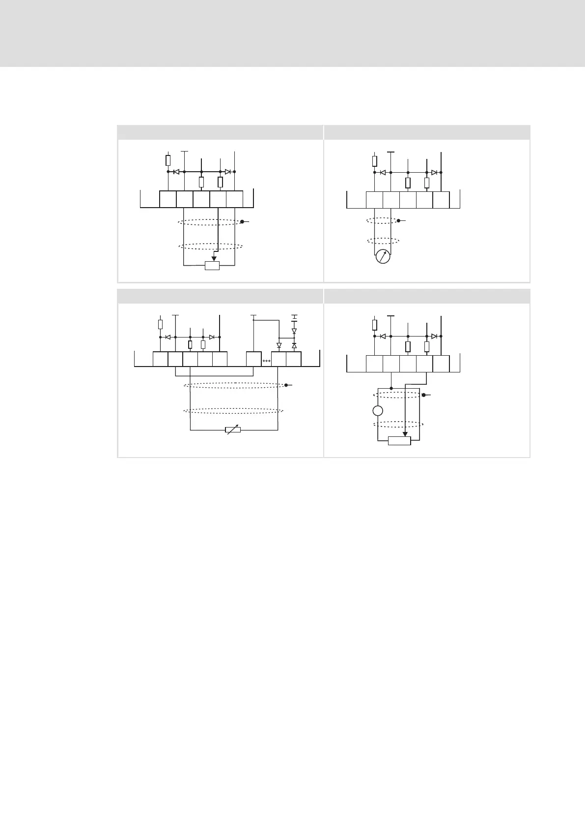
Fig. 6−33 Wiring examples of the analog inputs and outputs
0 Potentiometer with internal controller supply
1 Terminal assignment of the analog output signal, e.g. by a measuring
instrument
2 External master current selection based on a sensor signal 0 − 20 mA. If GA and
GIO are electrically connected, the digital cables have to be shielded as well.
3 Potentiometer with external supply
X3 Terminal for the analog inputs and outputs
X4 Terminal for the digital inputs and outputs
GA GND−A Ground reference potential for the analog inputs and outputs
GIO GND−IO Ground reference potential for the digital inputs and outputs
" EMC shield connection
U Measuring device
B Measuring transducer
Buy: www.ValinOnline.com | Phone 844-385-3099 | Email: CustomerService@valin.com
 Loading...

