1×counter/16×digital input
4
The modular system
4.23
L
4.23−2
EDSPM−TXXX−9.0−11/2009
1C/DI 16xDC24V
EPM – T430 1A
1
2.0
3.1
4.2
5.3
6.4
7.5
8.6
9.7
10.0
11.1
12.2
13.3
14.4
15.5
16.6
17.7
18
0
1
+
–
2
1
3
4
14
15
16
17
18
DC 24 V (DC 18 … 28.8 V)
.
A
B
epm−t128 epm−t131
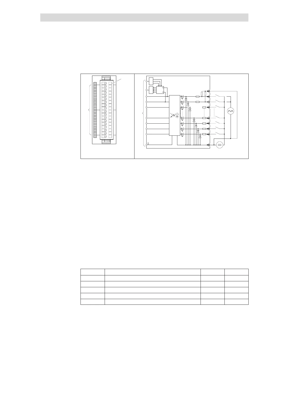
Fig. 4.23−2 Front view and connection 1×counter/16×digital input
2 × status display .0 ... .7; LED
(green) is lit when a HIGH level is
recognised
Terminal strip assignment details
1 GND (reference potential)
2 Digital input E.0 or counter
input A
3 Digital input E.1 or counter
input B
4 Digital input E.2
... ...
16 Digital input E.14
17 Digital input E.15
18 GND (reference potential)
Connection to backplane bus
Pre−assign the counter with a count
value
Output the current count value
32−bit counter with channel A and
channel B
Mode
Function E.0 E.1
0 4−fold pulse evaluation CLK CLK
1 Pulse and direction evaluation CLK DIR
2 Clock up/clock down evaluation CLK−UP CLK−DOWN
3 Frequency measurement CLK –
4 Period measurement CLK –
– No function
CLK Clock signal of a connected encoder
HIGH level starts and / or stops the counting process
CLK−UP Clock signal of a connected encoder
With each LOW−HIGH edge the counter counts up by 1
CLK−DOWN Clock signal of a connected encoder
With each LOW−HIGH edge the counter counts down by 1
DIR Indicates counting direction depending on signal level
LOW: Upcounter
HIGH: Downcounter
Status display and terminal
assignment
Counter mode overview
 Loading...