Parameterising analog modules
Parameter data
12
Parameter setting via system bus (CAN) / CANopen
12.3
12.3.1
L
12.3−4
EDSPM−TXXX−9.0−11/2009
For the 4xanalog input/output, up to 8 bytes of parameter data are available which
are assigned via SDOs. The following can be defined via the parameter data:
l The signal function for each input or output (current measurement, voltage
measurement, temperature measurement, or current signal output, voltage
signal output),
l The module error behaviour,
l The conversion speed.
Parameter setting via Global Drive Control (GDC):
Depending on the plug−in station, the module is activated via the indices
I3001
h
... I3010
h
(max. 16 analog modules). The parameter data are assigned in
the subindex 1 ... 3.
Parameter setting via CoDeSys:
The max. 16 analog modules are addressed via index I3401
h
. The parameter data
are assigned in the subindices 1 ... 64 (4 bytes per subindex). The module
4xanalog input/output assigns 3 subindices.
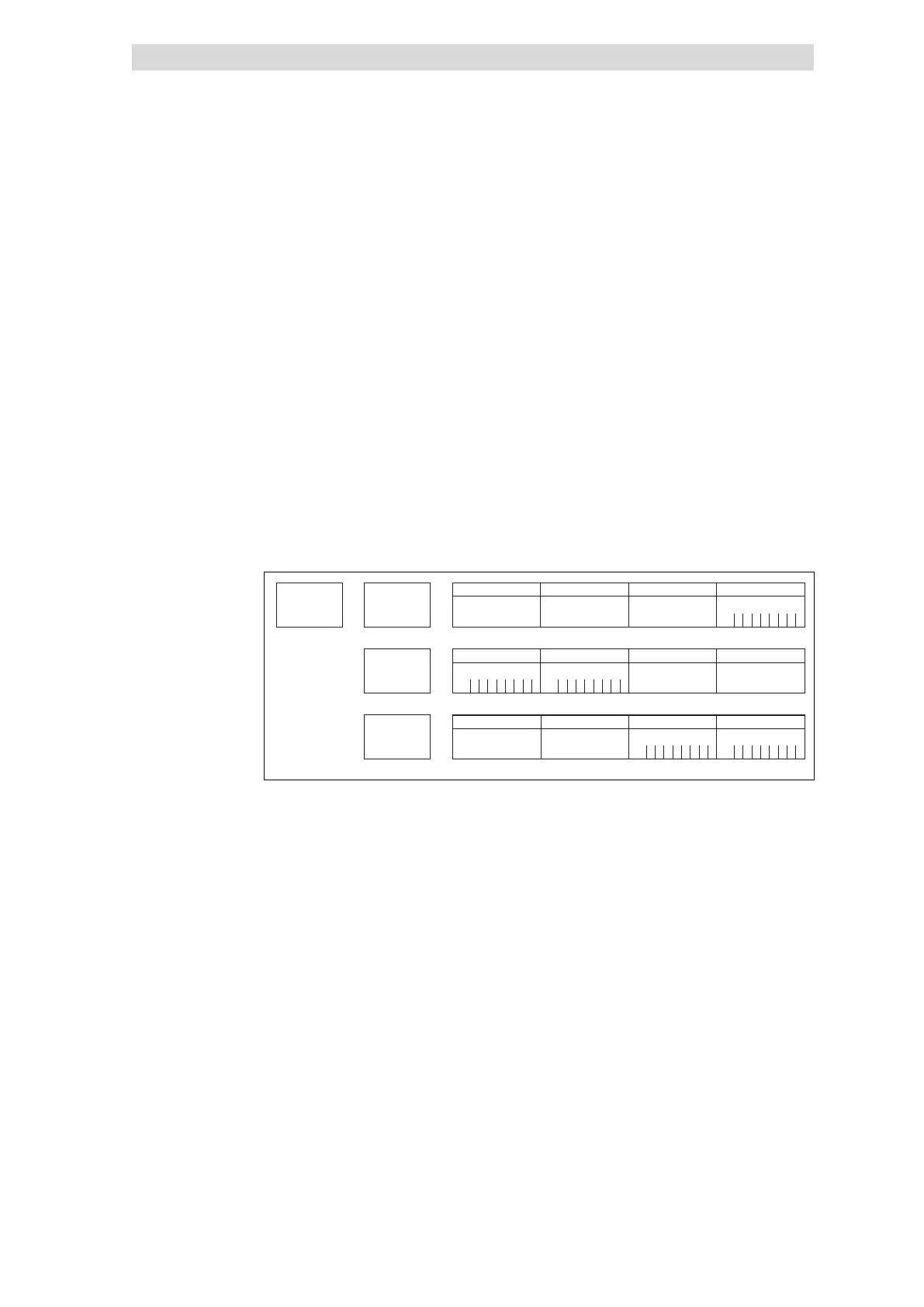
Index
I3xxx
h
Subindex
1
Subindex
2
Subindex
3
Byte 3
00
h
00
h
00
h
00
h
00
h
00
h
01
h
3B
h
3B
h
01
h
00
h
00
h
Byte 7
Byte 2
Byte 6
Byte 1
Byte 5
Byte 9Byte 11
Byte 0
Bit
BitBit
BitBit
0
00
00
1
11
11
2
22
22
3
33
33
4
44
44
5
55
55
6
66
66
7
77
77
Byte 4
Byte 8Byte 10
epm−t194
Fig. 12.3−3 Display of the parameter data 4xanalog input /output
4xanalog input/output module
 Loading...