Parameterising SSI interface
Process data assignment for "SSI mapping PLC" (I4104 = 0)
12
Parameter setting via system bus (CAN) / CANopen
12.5
12.5.3
L
12.5−6
EDSPM−TXXX−9.0−11/2009
12.5.3 Process data assignment for "SSI mapping PLC" (I4104 = 0)
This mapping is required for encoder value evaluation with Lenze PLC units and
function blocks of the "IO_System.lib".
Setting index I4104
h
= 0 (Lenze setting) adapts the input/output byte assignment
for communication with Lenze PLC units.
R
PDO
x
Data to module
Control
Data In HB
Data In MB
Data In LB
Status
Data Out HB
Data Out MB
Data Out LB
0
E/A.1
E/A.0
SSI
Encoder
011223344556677
Data from module
T
PDO
x
Gateway SSI-Interface
L
.0
.1
.2
.3
.4
.5
.6
.7
1
2
3
4
5
6
7
8
9
L
10
PW
ER
RD
BA
ADR.
0
1
DC
24V
X1
+24 V
Hold
E/A.0
epm−t172
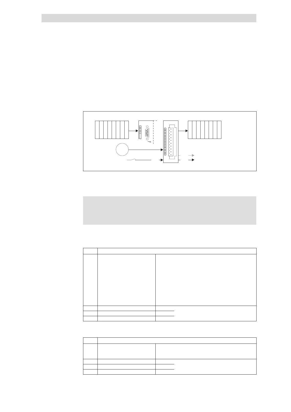
Fig. 12.5−8 Data input /output of SSI interface
For data input / output, four bytes are available which are transmitted (Rx PDO) or
output (Tx PDO) by PDOs.
) Note!
Input and output data get lost when the mains supply is switched
off/on; they are not stored!
The Rx PDO contains the input data used to control the outputs (I/O.0 and I/O.1)
depending on the encoder value.
Byte Assignment
0 Control Bits 0 ... 1
Setpoint selection
00: No setpoint selection
01: Setpoint selection for output I/O.0
10: Setpoint selection for output I/O.1
11: Setpoint selection for outputs I/O.0 and I/O.1
Bit 2 Reserved
Bit 3
Condition for setting the output = HIGH
0: If SSI encoder value is higher than setpoint
1: If SSI encoder value is lower than setpoint
Bits 4 ... 7 Reserved
1 Comparison value (HIGH byte) Bits 0 ... 7
Selection of comparison value
2 Comparison value (MID byte) Bits 0 ... 7
3 Comparison value (LOW byte) Bits 0 ... 7
The Tx PDO contains the output data supplied by the encoder.
Byte Assignment
0 Status
Bit 0 Status I/O.0
Bit 1 Status I/O.1
Bits 2 ... 7 Reserved
1 SSI encoder value (HIGH byte) Bits 0 ... 7
Output of SSI encoder value
2 SSI encoder value (MID byte) Bits 0 ... 7
3 SSI encoder value (LOW byte) Bits 0 ... 7
Input data
Output data
 Loading...