Elektrische Installation
Leitfrequenzeingang / Leitfrequenzausgang verdrahten
5
108
EDKVS9332X DE/EN/FR 8.0
Verdrahtung
Hinweis!
ƒ Wir empfehlen, für die Verdrahtung Lenze−Systemleitungen zu verwenden.
ƒ Bei selbstkonfektionierten Leitungen nur Leitungen mit paarweise
verdrillten und abgeschirmten Adern verwenden.
B
Enable (EN)
Lamp
control (LC)
GND
Z
1
2
3
4
5
6
7
8
9
1
2
3
4
5
6
7
8
9
A
X9X10
<50m
A
B
Z
A
A
B
Z
B
Z
9300VEC019
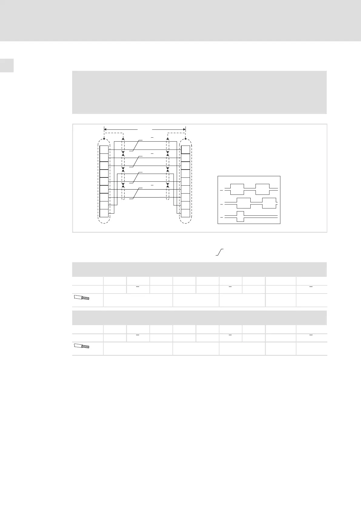
Abb. 5−35 Anschluss Leitfrequenzeingang (X9) / Leitfrequenzausgang (X10)
X9 Folgeantrieb (Slave) Signale bei Rechtslauf
X10 Leitantrieb (Master)
Paarweise verdrillte Adern
X9 − Leitfrequenzeingang
Steckverbinder: Stift, 9−polig, Sub−D
Pin 1
2 3 4 5 6 7 8 9
Signal B A A +5 V GND Z Z LC B
0,14 mm
2
(AWG 26)
0,5 mm
2
(AWG 20)
0,14 mm
2
(AWG 26)
0,5 mm
2
(AWG 20)
0,14 mm
2
(AWG 26)
X10 − Leitfrequenzausgang
Steckverbinder: Buchse, 9−polig, Sub−D
Pin 1
2 3 4 5 6 7 8 9
Signal B A A +5 V GND Z Z EN B
0,14 mm
2
(AWG 26)
0,5 mm
2
(AWG 20)
0,14 mm
2
(AWG 26)
0,5 mm
2
(AWG 20)
0,14 mm
2
(AWG 26)
 Loading...


