Electrical installation
Wiring of the control connections
Terminal assignment
5
205
EDKVS9332X DE/EN/FR 8.0
5.8.5 Terminal assignment
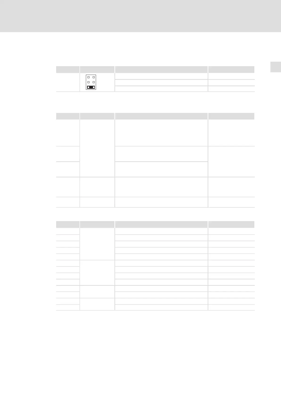
Analog input configuration
Terminal Jumper strip X3 Jumper setting Possible levels
X6/1, X6/2
1
3
5
2
4
6
1−2
1)
−10 V ... +10 V
1)
3−4 −10 V ... +10 V
5−6 −20 mA ... +20 mA
1)
Lenze setting (delivery state)
Non−configurable control terminals
Terminal Description Function Level / state
X11/K32
X11/K31
Safety relay K
SR
1st disconnecting
path
Pulse inhibit feedback
Open contact: pulse
inhibit is inactive
(operation)
Closed contact: pulse
inhibit is active
X11/33 – coil of safety relay K
SR
Coil is not carrying any
current: pulse inhibit is
active
X11/34 + coil of safety relay K
SR
Coil is carrying current:
pulse inhibit is inactive
(operation)
X5/28 Controller inhibit
(DCTRL−CINH)
2nd disconnecting
path
Controller enable/inhibit LOW: Controller
inhibited
HIGH: Controller enabled
X5/ST1
X5/ST2
STATE−BUS
Lenze setting of the configurable control connections for the 9300 Servo PLC
Terminal Description Function Level
X5/E1
Digital inputs
Not assigned HIGH
X5/E2 Not assigned HIGH
X5/E3 Not assigned HIGH
X5/E4 Not assigned HIGH
X5/E5 Not assigned HIGH
X5/A1
Digital outputs
Not assigned HIGH
X5/A2 Not assigned HIGH
X5/A3 Not assigned HIGH
X5/A4 Not assigned HIGH
X6/1, X6/2
Analog inputs
Not assigned −10 V ... +10 V
X6/3, X6/4 Not assigned −10 V ... +10 V
X6/62
Analog outputs
Not assigned −10 V ... +10 V
X6/63 Not assigned −10 V ... +10 V
 Loading...


