Electrical installation
Wiring of the control connections
Terminal data
5
207
EDKVS9332X DE/EN/FR 8.0
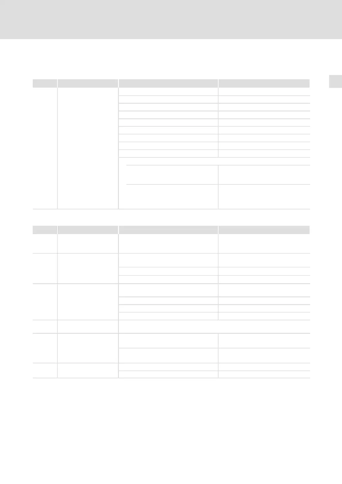
5.8.6 Terminal data
Safety relay K
SR
Terminal Description Field Values
X11/K32
X11/K31
X11/33
X11/34
Safety relay K
SR
1st disconnecting path
Coil voltage at +20 °C DC 24 V (20 ... 30 V)
Coil resistance at +20 °C 823 W ±10 %
Rated coil power Approx. 700 mW
Max. switching voltage AC 250 V, DC 250 V (0.45 A)
Max. AC switching capacity 1500 VA
Max. switching current (ohmic load) AC 6 A (250 V), DC 6 A (50 V)
Recommended minimum load > 50 mW
Max. switching rate 6 switchings per minute
Mechanical service life 10
7
switching cycles
Electrical service life
at 250 V AC
(ohmic load)
10
5
switching cycles at 6 A
10
6
switching cycles at 1 A
10
7
switching cycles at 0.25 A
at 24 V DC
(ohmic load)
6 × 10
3
switching cycles at 6 A
10
6
switching cycles at 3 A
1.5 × 10
6
switching cycles at 1 A
10
7
switching cycles at 0.1 A
Digital inputs, digital outputs
Terminal Description Field Values
X5/28 Controller inhibit
(DCTRL−CINH)
2nd disconnecting path
PLC level, HTL LOW: 0 ... +3 V
HIGH: +12 ... +30 V
X5/E1
X5/E2
X5/E3
X5/E4
X5/E5
Digital inputs
PLC level, HTL LOW: 0 ... +3 V
HIGH: +12 ... +30 V
Input current per input 8 mA for +24 V
Cycle time 1 ms
X5/A1
X5/A2
X5/A3
X5/A4
Digital outputs
PLC level, HTL LOW: 0 ... +3 V
HIGH: +12 ... +30 V
Load capacity per output Maximally 50 mA
Load resistance For +24 V at least 480 W
Cycle time 1 ms
X5/39 GND2 Reference potential for digital signals
Isolated to X6/7 (GND1)
X5/59 Connection of external
voltage source for backup
operation of the drive
controller in the case of
mains failure
Input voltage DC 24 V (+18 ... +30 V)
Current consumption Maximally 1 A for 24 V
X5/ST1
X5/ST2
STATE−BUS
Maximum number of nodes 20
Maximum length of the bus cable 5 m
 Loading...


