Electrical installation
Standard devices in the power range 15 ... 30 kW
Motor connection
5
179
EDKVS9332X DE/EN/FR 8.0
Characteristics of the connection for motor temperature monitoring:
Terminals T1, T2
Connection
l PTC thermistor
– PTC thermistor with defined tripping temperature (acc. to DIN 44081 and
DIN 44082)
l Thermal contact (NC contact)
– Thermostat as NC contact
Tripping point l Fixed (depending on the PTC/thermal contact)
l PTC: RJ
> 1600 W
l Configurable as warning or error (TRIP)
Notes l Monitoring is not active in the Lenze setting.
l If you do not use a Lenze motor, we recommend the use of a PTC thermistor up
to 150°C.
PE
PE
T1
T1
T2
T2
U
VW
4
4
T1
T2
2.5 Nm
22,1 lb-in
T1
T2
2.5 Nm
22,1 lb-in
}
+
PE
}
+
PE
0
0
1
1
3
2
2
U, V, W,
PE
5 Nm
44 lb-in
M 6
9300std030
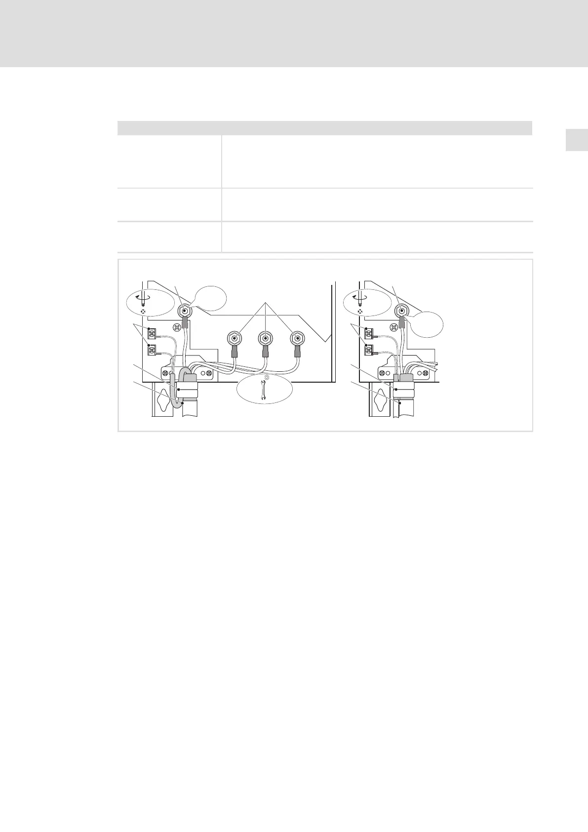
Fig. 5−12 Motor connection with PTC thermistor or thermal contact (NC contact)
Motor connection with Lenze system cable with integrated control cable for the motor
temperature monitoring
Shield sheet
Clamp entire shield and shield of the control cable for the motor temperature monitoring
with the straps. If required, fix by means of cable tie.
Motor cable connection and separate control cable for the motor temperature monitoring
Shield sheet
Clamp shield of the motor cable and shield of the cable for the motor temperature
monitoring with the straps. If required, fix by means of cable tie.
PE stud
PE cable connection with ring cable lug
U, V, W
Motor cable connection
Check the correct polarity. Observe maximum length of the motor cable.
Max. connectable cable cross−section: 50 mm
2
with ring cable lug
T1, T2 for motor temperature monitoring
Cable connection for PTC thermistors or thermal contacts (NC contacts)
 Loading...


