Electrical installation
Standard devices in the power range 55 ... 75 kW
Motor connection
5
195
EDKVS9332X DE/EN/FR 8.0
Characteristics of the connection for motor temperature monitoring:
Terminals T1, T2
Connection
l PTC thermistor
– PTC thermistor with defined tripping temperature (acc. to DIN 44081 and
DIN 44082)
l Thermal contact (NC contact)
– Thermostat as NC contact
Tripping point l Fixed (depending on the PTC/thermal contact)
l PTC: RJ
> 1600 W
l Configurable as warning or error (TRIP)
Notes l Monitoring is not active in the Lenze setting.
l If you do not use a Lenze motor, we recommend the use of a PTC thermistor up
to 150°C.
T1
T2
PE
U
VW
2
3
4
M4 x 12: 2.5 Nm (22.1 lb-in)
M5 x 12: 3 Nm (26.5 lb-in)
U, V, W,
PE
M10
30 Nm
264 lb-in
1
0
T1
T2
2.5 Nm
22.1 lb-in
5
}
+
PE
9300std032
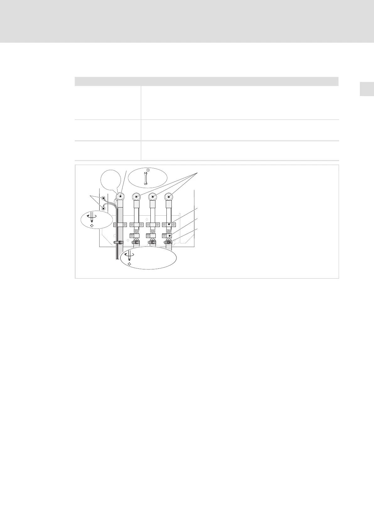
Fig. 5−22 Motor connection with PTC thermistor or thermal contact (NC contact)
PE stud
PE cable connection with ring cable lug
U, V, W
Motor cable connection
Check the correct polarity. Observe maximum length of the motor cable.
Max. connectable cable cross−section: 240 mm
2
with ring cable lug
Cable clamps for strain relief of motor cable
Fasten cable clamps with M4 × 12 mm screws
Shield clamps
Place shields of motor cable with large surface on the shield sheet and fasten with shield
clamps and M5 × 12 mm screws
Cable ties for additional strain relief of motor cable
T1, T2 for motor temperature monitoring
Cable connection for PTC thermistors or thermal contacts (NC contacts)
Place shield with large surface on PE stud
 Loading...


