3 Product description
Overview
14 Lenze · Inverter i510 / i550 - Cabinet · Operation Manual · 0.4 EN · 02/2016
3.2 Overview
Get familiar with the two inverter types on the following overview images.
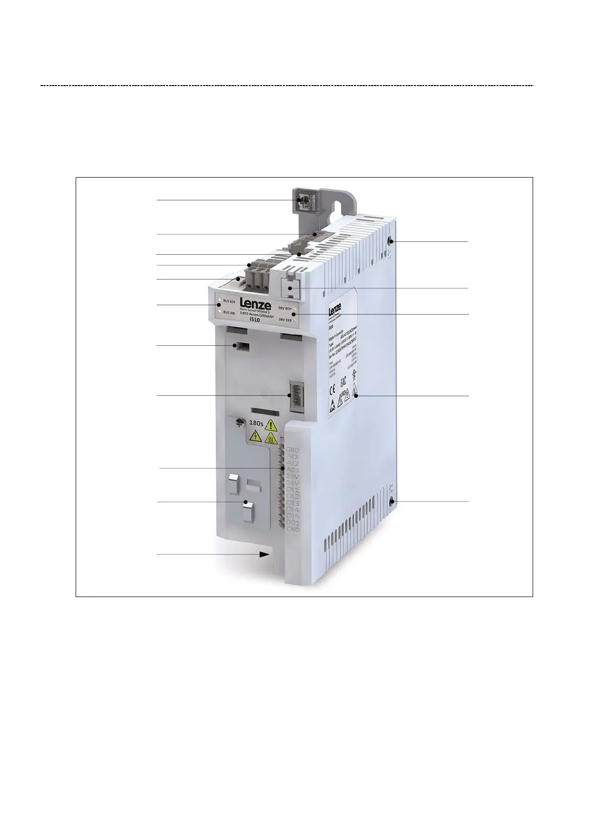
3.2.1 i510 inverter overview
Fig. 3: i510 inverter overview
1) X3 – Control terminal (Basic I/O)
2) X9 – Relay output
3) X16 – Interface for diagnostic module
4) X20 - Memory module
5) X100 – Mains connection
6) X105 – Motor connection
7) X216 – Network (Option)
8) Switch between CANopen/Modbus
9) Rating plate
10) Inverter status LEDs
11) Network status LEDs
12) PE / Ground connection
13) Shield connection (CANopen/Modbus)
14) Shield connections for control connections
15) IT screw (from 0.55 kW)
12
5
2
7
13
11
8
3
1
14
6