3 Product description
Overview
Lenze · Inverter i510 / i550 - Cabinet · Operation Manual · 0.4 EN · 02/2016 15
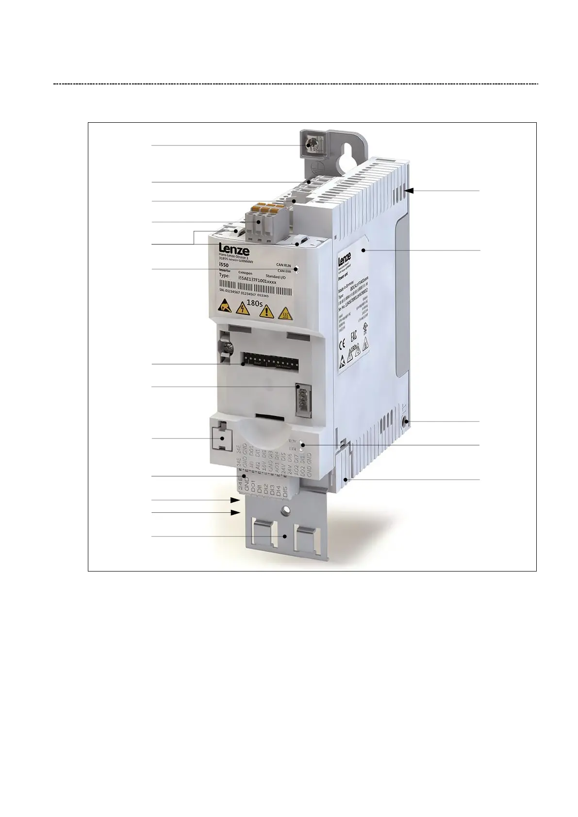
3.2.2 i550 inverter overview
Fig. 4: i550 inverter overview
1) X1 – Safety module (Option)
2) X3 – Control terminal (standard I/O or application I/O)
3) X9 – Relay output
4) X16 – Interface for diagnostic module
5) X20 – Memory module
6) X100 – Mains connection and
DC-Link connection (Only 3Ph/400V power units)
7) X105 – Motor and brake resistor connection
8) X109 – PTC input
9) X2xx – Network (Option)
10) DIP switch for baud rate and bus address
(CANopen, Modbus, PROFIBUS)
11) Rating plate
12) Inverter status LEDs
13) Network status LEDs
14) Shield connection (CANopen/Modbus)
15) Shield connections for control connections
16) PE / Ground connection
17) IT screw (from 0.55 kW)
16
6
3
9
14
13
10
4
5
2
7
8
15