6 Function & parameter description
Control concept
Lenze · Inverter i510 / i550 - Cabinet · Operation Manual · 0.4 EN · 02/2016 39
6.2.3 Control examples
The inverter can be configured with different Run/Start/Stop signals. The following 3 examples show the most
commonly used signals with the corresponding parameters and a signal flow chart which explains in detail the
behavior of the inverter.
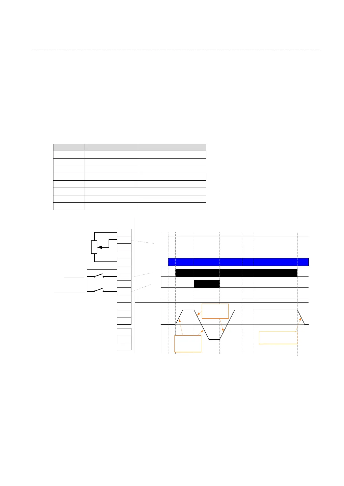
Run/Stop (One Signal)
Using one signal Run/Stop to start and stop the inverter. Run/Stop Level High will start the inverter, Level
Low will stop the inverter according to the selected stop method (P203:3)
Invert Rotation Level High will change the motor direction
GND
AO1
AI2
AI1
DI1
24V
10V
DI5
DI4
DI3
DI2
GND
DO1
Run/Stop
Invert rotation
Control Wiring
P400:2
P400:13
NO
COM
NC
1k … 10k
Potentiometer
DI1
DI3
Expected Behavior
50 Hz
AI1
Mains
50 Hz
0 Hz
-50 Hz
P220:0
Acceleration
time 1
P221.00
Deceleration
time 1
Stop method based
on P203:3 setting
Motor
Frequency