6 Function & parameter description
Group 4 – I/O setup
80 Lenze · Inverter i510 / i550 - Cabinet · Operation Manual · 0.4 EN · 02/2016
0.0 ... [0.0] ... 100.0 %
Configuration of the deadband such that any input value below this per-
centage will be treated as 0Hz. (In % of Max Input Value)
Example: Deadband 10% of 50Hz:
-10V … 10V Deadband -5Hz … 5 Hz
0 … 10V Deadband 0Hz … 5 Hz
Analog input 2: Monitoring level
-100.0 ... [0.0] ... 100.0 %
Monitoring condition of the analog input
Analog input 2: Monitoring action
0: Below level 1
1: Above level 1
Monitoring condition of the analog input
Analog input 2: Error response
3:Fault
(Reference see P310:1)
Fault reaction of the analog input monitoring.
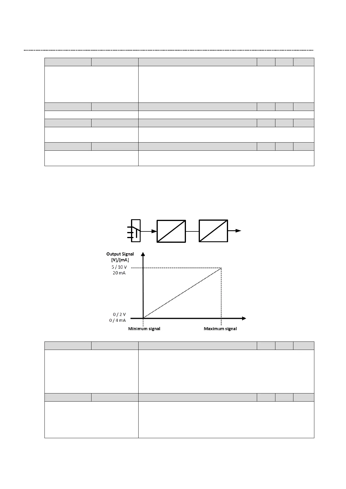
6.6.9 Analog output settings
The analog output can be used to send a feedback signal to the control system (I. e. Motor current, Actual Fre-
quency, …). Different functions and output configurations are available.
Unit
V/I
Output configuration
Scaling
Functionality
0: Disabled
1: 0...10VDC
2: 0...5VDC
3: 2...10VDC
4: 4...20mA
5: 0...20mA
Configuration of Analog output signal 1
0: Not connected
1: Output frequency
2: Frequency setpoint
3: Analog input 1
4: Analog input 2
Analog output function1
Scaling factors:
1: [0.1 Hz]
2: [0.1 Hz]