6 Function & parameter description
Control concept
38 Lenze · Inverter i510 / i550 - Cabinet · Operation Manual · 0.4 EN · 02/2016
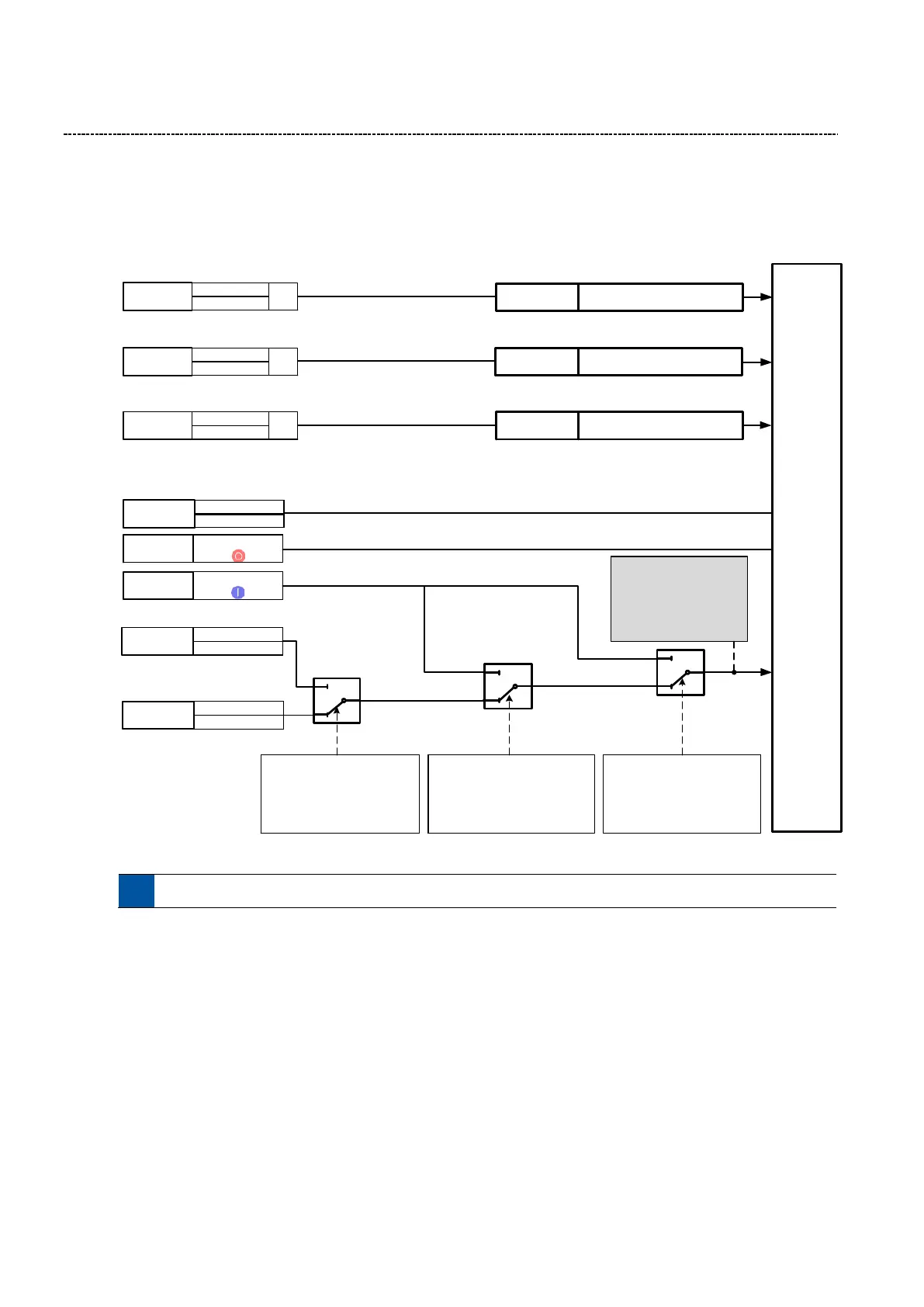
6.2.2 Control Source
The i500 can be controlled from various locations like digital IO’s, keypad or network. The following graphic gives
an overview of the parameters and their influence.
Motor
Control
I) Inverter Enable / Run/Stop / Quick Stop
II) Start / Stop / JOG
Drive Inhibit
Disable Drive Output
=> «Coast to Stop»
Quick Stop
Decelerate with Quick Stop Ramp
to zero
1
0
Keypad control
P400:12 (0x2631:12)
0 = FALSE (Normal Drive Operation)
1 = TRUE (Keypad Active)
… Other options / external triggers
1
0
Network enable
P400:37 (0x2631:37)
0 = FALSE (Connection List Active)
1 = TRUE (Network Active)
… Other options / external triggers
Control source
P200:0 (0x2824:0)
0 = Flexible
1 = Keypad ONLY
1
0
Active control source
(STATUS)
P125:1 (0x282B:1)
0: Flexible
1: Network
2: Keypad
Start method
P203:1
(0x2838:1)
Stop method
P203:3
(0x2838:3)
STOP
Keypad
Start Fwd/Rev
Network
Run Fwd/Rev
Drive Strop
Stop method
P203:3 (0x2838:3)
f
Jog forward (CW)
Jog
Jog reverse (CCW)
Start Fwd
Keypad
Start Fwd/Rev
Connection
list
Run Fwd/Rev
Connection List
Network
OR
Inverter
Enable
Connection List
Network
OR
Run/Sop
Connection List
Network
OR
Quick stop
(QSP)
The actual control source can be seen in P125:1