9 Troubleshooting
LED status display
Lenze · Inverter i510 / i550 - Cabinet · Operation Manual · 0.4 EN · 02/2016 117
9 Troubleshooting
9.1 LED status display
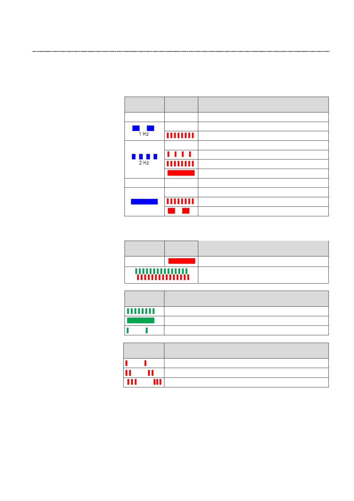
The inverter has two LEDs
(RDY = READY, ERR =
ERROR) on the front cover
to identify the status of the
inverter:
STO active, warning active
Inverter inhibited, DC Voltage not
Inverter inhibited, Warning active
Inverter inhibited, Fault active
Inverter released, drive running OR Quick Stop active
Inverter released, drive running, Warning active
Inverter released, Trouble reaction active
9.2 CAN LED status display
The LED CAN-RUN and CAN-
ERR in combination indicate
when the inverter is not yet
active on the CAN-Bus.
Inverter not active on CAN-Bus / Bus OFF
Automatic baud rate detection
In general the LED CAN-RUN
indicates CANopen state
In general the LED CAN-ERR
indicates error states:
Sync Message Error (Can only occur in state “Operational”)

 Loading...


