6 Function & parameter description
Group 3 – Motor control
Lenze · Inverter i510 / i550 - Cabinet · Operation Manual · 0.4 EN · 02/2016 59
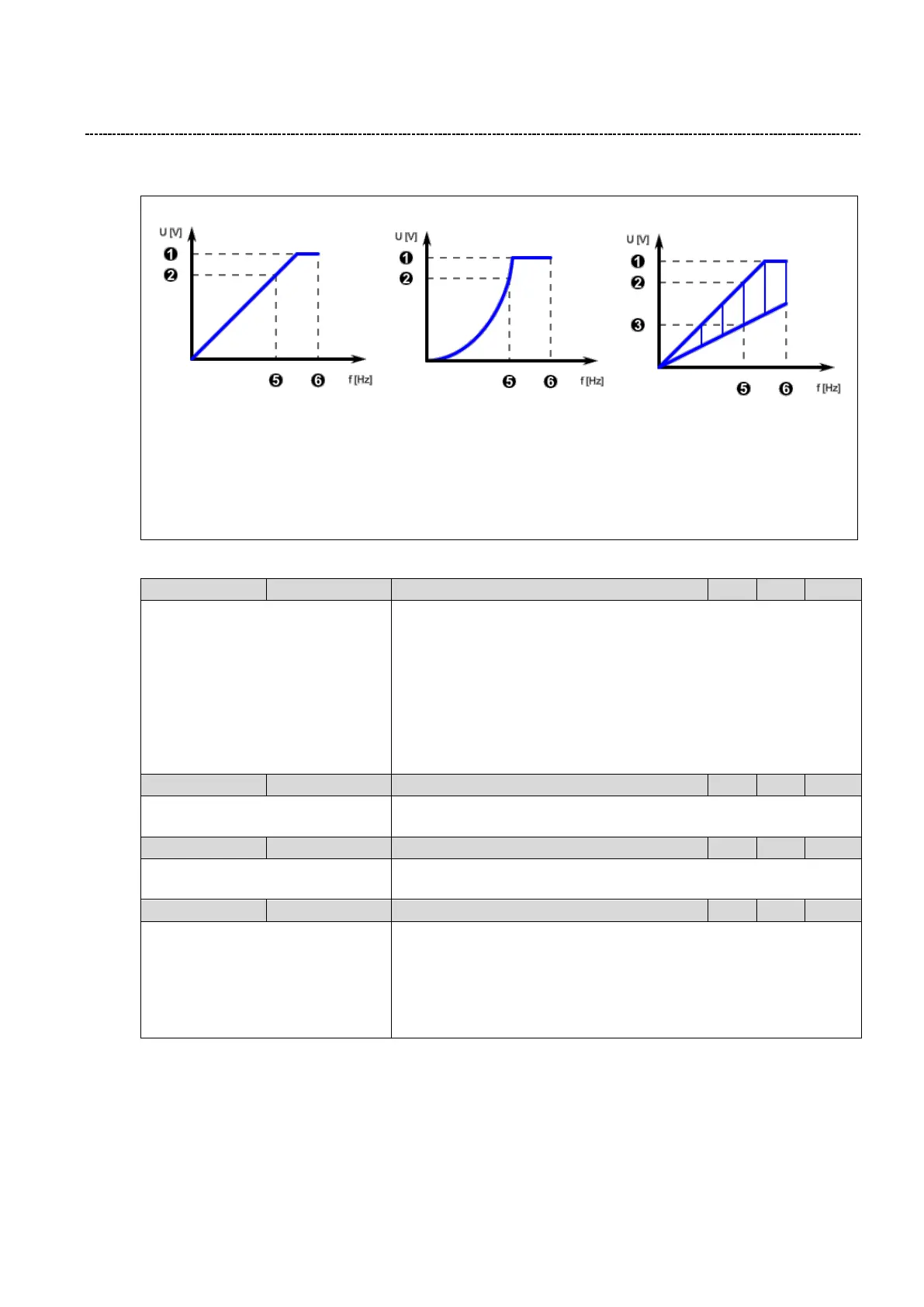
6.5.2 V/f: Curve setting
P302 = 0: Linear P302: Quadratic P302: Eco
1: P208:1 Rated mains voltage
2: P303:1 Base Voltage
3: P330:1 VFC-ECO: Minimum Voltage
5: P303:2 Base Frequency
6: P211:0 Maximum Frequency
Fig. 18: V/F mode
0: Linear
1: Quadratic
3: Eco
Configuration of V/f shape
0: Linear
The curve has a constant V/f ratio which provides constant torque in the
motor. V/f curves are used in many general applications.
1: Quadratic
The curve V/f is a quadratic function. This is used for fan or pump appli-
cations.
3: Eco
Energy Saving Control for Asynchronous Motor
0 ... [Type Code dependent] ... 5000 V
V/f Base Voltage
To be set to motor nominal voltage
0 ... [Type Code dependent] ... 599 Hz
V/f Base Frequency
To be set to motor nominal frequency
Minimum voltage (Only used for Eco Mode)
The efficiency range of VFC Eco is limited by the standard U/f curve and
the VFC Eco curve. (See graphic above)
This parameter describes the operating point in relation to a chosen per-
centage value of Base voltage (P303:1) at Base frequency (P303:2). See
graphic above.