4 Installation
Electrical installation
20 Lenze · Inverter i510 / i550 - Cabinet · Operation Manual · 0.4 EN · 02/2016
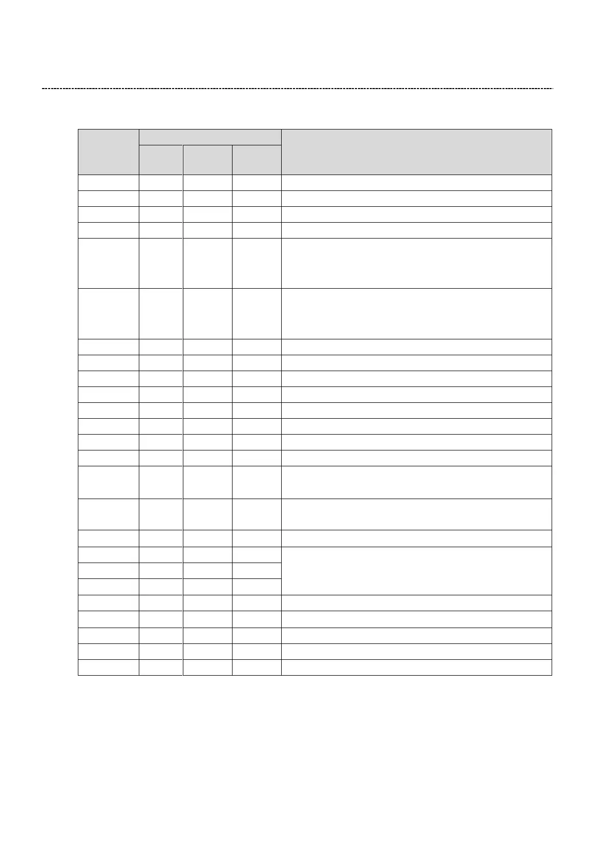
4.2.3 Control wiring i510/i550
Connection point for external 24 VDC control power
Ground / earth reference for analog and digital I/O
Programmable digital output (24 VDC)
Programmable digital output (24 VDC)
Analog input:
i510: 0…5/10 VDC, 0/4…20 mA (uni-directional)
i550: -10/-5…0…5/10 VDC (bi-directional),
0/4…20 mA (uni-directional)
Analog input:
i510: 0…5/10 VDC (uni-directional)
i550: -10/-5…0…5/10 VDC (bi-directional),
0/4…20 mA (uni-directional)
10 VDC, 10 mA supply for reference potentiometer
Programmable digital input (<5V = Low, >15V = High)
Programmable digital input (<5V = Low, >15V = High)
Programmable digital input (<5V = Low, >15V = High)
Programmable digital input (<5V = Low, >15V = High)
Programmable digital input (<5V = Low, >15V = High)
Programmable digital input (<5V = Low, >15V = High)
Programmable digital input (<5V = Low, >15V = High)
Programmable analog output:
0…10 VDC, 0/4…20 mA (scalable, gain, offset, deadband)
Programmable analog output:
0…10 VDC, 0/4…20 mA (scalable, gain, offset, deadband)
24 VDC, 100 mA customer use and reference for DIs
Programmable form "C" relay output:
COM = Common, NC = Normally Closed, NO = Normally Open
30 VDC, 250 VAC @ 2 A
PTC thermal sensor input 1
PTC thermal sensor input 2
STO (safety) ground / earth reference
*Terminal are internally connected and ca be used for loop wiring