6 Function & parameter description
Group 4 – I/O setup
76 Lenze · Inverter i510 / i550 - Cabinet · Operation Manual · 0.4 EN · 02/2016
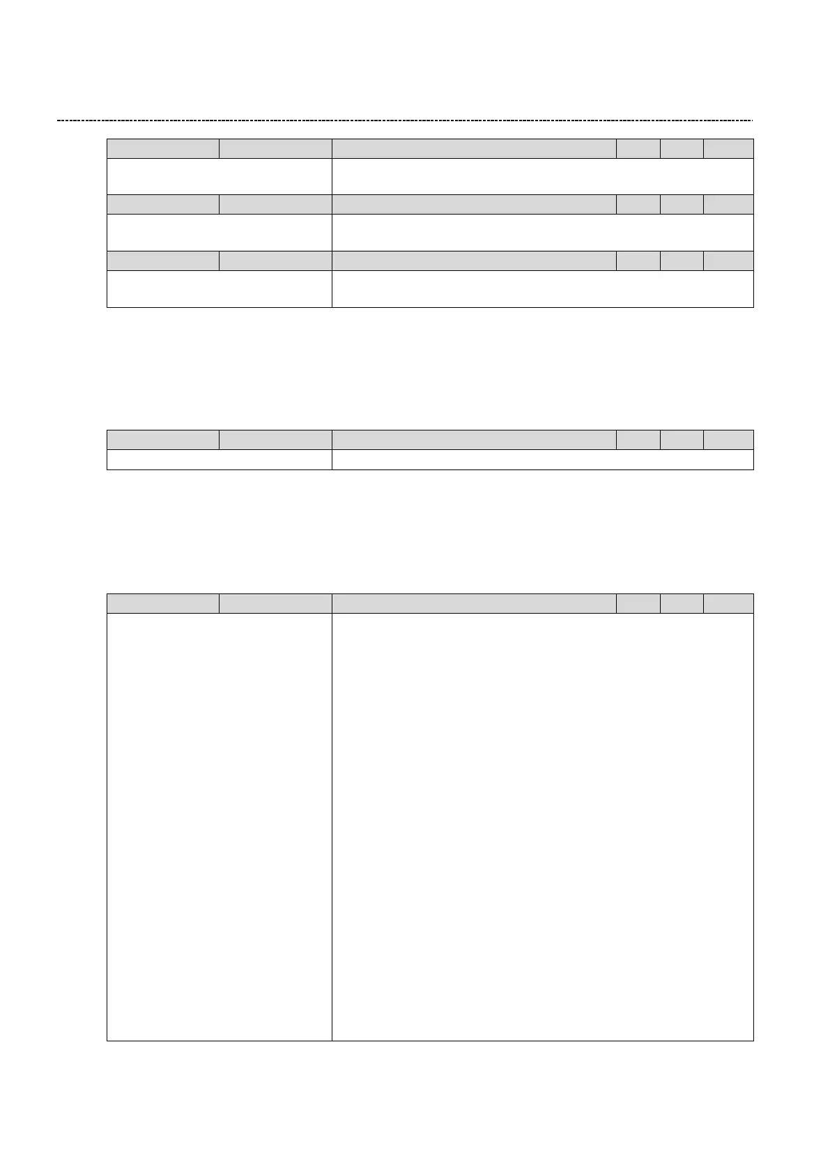
0: Not inverted
1: Inverted
Inversion of Digital Input
0: Not inverted
1: Inverted
Inversion of Digital Input
0: Not inverted
1: Inverted
Inversion of Digital Input
6.6.6 Frequency threshold setup
A frequency threshold can be used to trigger a function, a digital output or the relay. The trigger is referenced to
actual inverter output frequency. This trigger is TRUE when the actual output frequency is above a programmable
frequency threshold.
0.0 ... [0.0] ... 599.0 Hz
6.6.7 Digital output configuration
The digital outputs (Relay, DO) can be configured:
Functionality can be selected
Inversion of Output (Only Relay and DO)
0: Not connected
1: Constant TRUE
11: Digital input 1
12: Digital input 2
13: Digital input 3
14: Digital input 4
15: Digital input 5
16: Digital input 6 (*)
17: Digital input 7 (*)
34: NETWordIN2 - bit 0
35: NETWordIN2 - bit 1
36: NETWordIN2 - bit 2
37: NETWordIN2 - bit 3
38: NETWordIN2 - bit 4
39: NETWordIN2 - bit 5
40: NETWordIN2 - bit 6
41: NETWordIN2 - bit 7
42: NETWordIN2 - bit 8
43: NETWordIN2 - bit 9
44: NETWordIN2 - bit 10
45: NETWordIN2 - bit 11
46: NETWordIN2 - bit 12
47: NETWordIN2 - bit 13
48: NETWordIN2 - bit 14
49: NETWordIN2 - bit 15
0: Not Connected / always false
1: TRUE always
11-17: TRUE when corresponding digital input is asserted
34-49: TRUE when selected bit of the NETWordIn is high.
50: TRUE when the inverter is running.
FALSE when inverter is disabled, DC-Brake active, quick stopped and
speed <0,2Hz, faulted or stopped.
51: TRUE when inverter not in Failure, Safety OK and DC link charged
(SW 02.01)
52: TRUE when the inverter is enabled.
53: TRUE when inverter is enabled, output=0V, not running and not
faulted
54: TRUE when quick stop is selected and active.
55: TRUE when Safe Torque OFF is active
56: TRUE when the inverter has a fault condition.
57: TRUE when the inverter has a fault condition that is locked and can-
not be reset.
58: TRUE when a warning is present.
59: TRUE when a trouble condition is present.
60: TRUE when the heat sink temperature exceeds the warning level
65: TRUE when a PTC fault is detected.
66: TRUE when a flying start or a restart is active
67: TRUE when the DC brake is on.
69: TRUE when output frequency is negative
70: TRUE when the output frequency is > the frequency threshold