6 Function & parameter description
Group 7 – Auxiliary Functions
Lenze · Inverter i510 / i550 - Cabinet · Operation Manual · 0.4 EN · 02/2016 89
Motor failure or damage
During DC-Brake the motor heats up.
DC Braking should only be used in applications where the load is stopped infrequently and should only
be applied for the minimum time required possible.
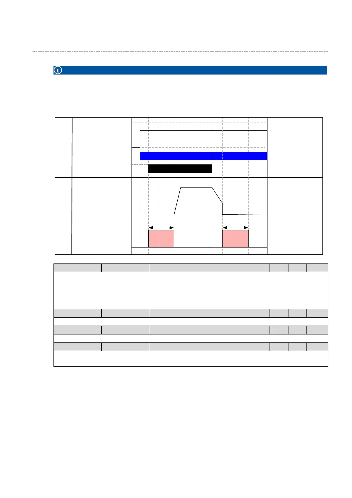
Speed
Command
0 Hz
60 Hz
40 Hz
Input Signals /
Conditions
Output
Run / Stop
Mains Power
0 Hz
DC
Brake
Motor
Speed
P704:2
DC
Brake
P704:2
P704:3
0:Not connected
(Reference see P400:1)
Manual DC Brake activation signal
Level:
TRUE: DC brake will be active.
FALSE: DC brake will be deactivated.
0.0 ... [0.0] ... 200.0 %
DC Brake current as of % of motor rated current
0.0 ... [0.0] ... 999.9 s
0.0 ... [0.0] ... 599.0 Hz
Frequency Threshold to apply the DC Brake during deceleration of mo-
tor.