Protocols for position value output
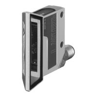
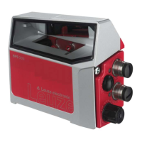
Leuze electronic BPS 8 100
TNT 35/7-24V
9.3.3 BPS 8 SM 10x-03 response telegram
The response telegram consists of 5 bytes.
Response telegram structure
Description
In the response to a position data request, the bits CALC, DB and SLEEP are set as follows:
• CALC = 1
• DB = 0
• SLEEP = 0
Byte no. Designation Bit 7 Bit 6 Bit 5 Bit 4 Bit 3 Bit 2 Bit 1 Bit 0
0 Status byte 0 SLEEP A1 A0 CALC DB OUT ERR
1 Data byte 1 0 P20 P19 P18 P17 P16 P15 P14
2 Data byte 2 0 P13 P12 P11 P10 P09 P08 P07
3 Data byte 3 0 P06 P05 P04 P03 P02 P01 P00
4 XOR combination Bitwise exclusive OR combination of bytes 0 to 3
Byte Bit Name Function Description
0
0
ERR Internal error 1 = An internal error has occurred
0 = No error exists
1
OUT Tape error 1 = No bar code decodable
0 = Bar code decodable
2
DB Diagnostic response flag 0 = No diagnostic data
1 = The data bytes contain the diagnostic data
3
CALC Position/diagnostic data flag 1 = Response to request for position or diagnostic data
4
A0 Address A1A0 in
RS 485 network
00 = Address 0
01 = Address 1
5
A1 10 = Address 2
11 = Address 3
6
SLEEP Standby state 1 = Device is in Standby mode (see request telegram)
0 = Device is in positioning mode
7 – None Without function, bit permanently set to zero
1…3
0…8
Data,
P20 … P00
Data Depending on the request, the data is transferred here; either posi-
tion data, diagnostic data or marker data.
40…8XOR XOR combination Bitwise exclusive OR combination of bytes 0 to 3