Electrical connection
Leuze electronic BPS 8 57
TNT 35/7-24V
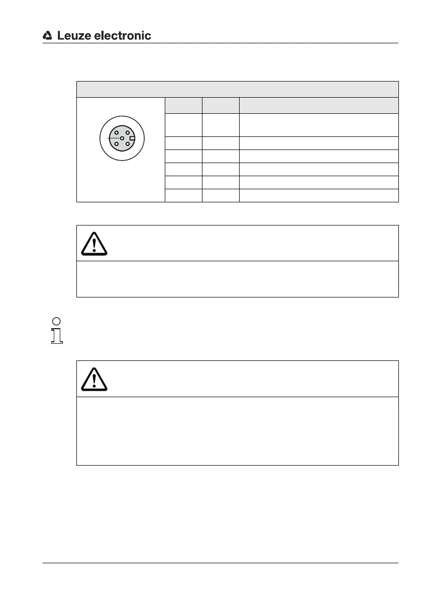
7.4.2 SW IN/OUT socket – switching input and switching output
Figure 7.8: MA 8-01/MA 8-02 – Pin assignment SW IN/OUT socket
The switching input/switching output are programmed via the parameters in the BPS
Configuration Tool configuration software. For further information, see Chapter 8.2,
Page 62 et seq.
SW IN/OUT (5-pin socket, A-coded)
Pin Name Comment
1VOUT
Voltage supply for sensor system (VOUT
identical to VIN at PWR IN)
2SWOUTSwitching output
3GNDGND for the sensor system
4SWINSwitching input
5FEFunctional earth
Thread FE Functional earth (housing)
CAUTION
Degree of protection IP 67!
Degree of protection IP 67 is achieved only if the connectors and caps are screwed into
place!
CAUTION
Connecting a sensor with standard M12 connectors!
If you use a sensor with a standard M 12 connector, please note the following:
Use only sensors on which the switching output does not lie on pin 2 or sensor
cables on which pin 2 is not assigned. Otherwise, the switching output is not pro-
tected against feedback on the switching input. If the inverted sensor output lies on
pin 2, erroneous behavior of the switching output will result.
1
23
4
5
SWIN VOUT
GND
FE
SWOUT
SW IN/OUT