Protocols for position value output
Leuze electronic BPS 8 86
TNT 35/7-24V
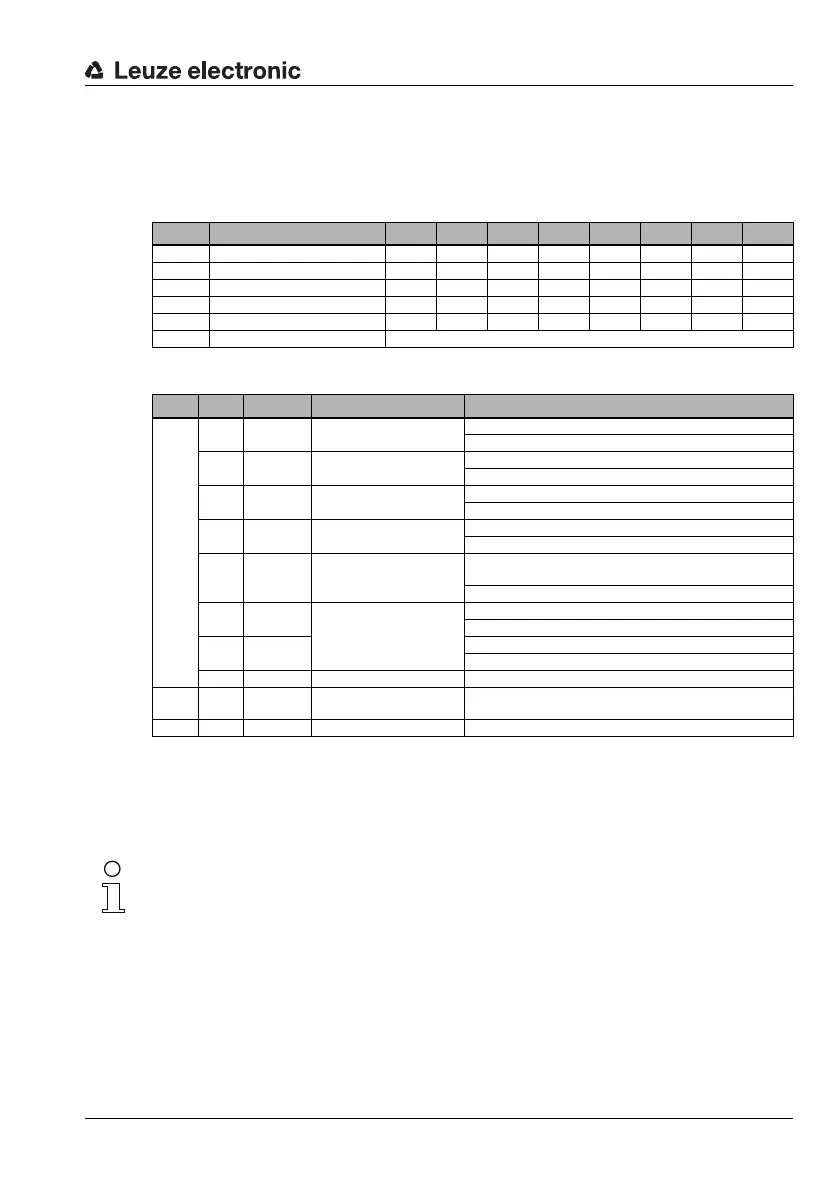
9.1.3 BPS 8 SM 10x-01 / BPS 8 SM 10x-05 response telegram
The response telegram consists of 6 bytes.
Response telegram structure
Description
Position data
The position data are output in two's complement as a 32-bit signed integer value by
default in millimeters with a resolution of 1 mm (see chapter 8.5.2 "Position detection")
The P00 data bit corresponds to the LSB, the P31 data bit corresponds to the MSB.
Byte no. Designation Bit 7 Bit 6 Bit 5 Bit 4 Bit 3 Bit 2 Bit 1 Bit 0
0 Status byte 0 Q1 Q0 SLEEP MM D OUT ERR
1 Data byte 1 P31 P30 P29 P28 P27 P26 P25 P24
2 Data byte 2 P23 P22 P21 P20 P19 P18 P17 P16
3 Data byte 3 P15 P14 P13 P12 P11 P10 P09 P08
4 Data byte 4 P07 P06 P05 P04 P03 P02 P01 P00
5 XOR combination Bitwise exclusive OR combination of bytes 0 to 4
Byte Bit Name Function Description
0
0
ERR Internal error 1 = An internal error has occurred
0 = No error exists
1
OUT Tape error 1 = No bar code decodable
0 = Bar code decodable
2
D Diagnostic data exist 1 = Diagnostic data are present in the memory
0 = No diagnostic data exists
3
MM Marker bar code present 1 = The content of a marker bar code is in the memory
0 = No content of a marker bar code in the memory
4
SLEEP Standby state 1 = Device is in Standby mode
(see request telegram)
0 = Device is in positioning mode
5
Q0 Reading quality Q1Q0 00 = Reading quality > 75%
01 = Reading quality 75% … 50%
6
Q1 10 = Reading quality 50% … 25%
11 = Reading quality < 25%
7 – None Without function, bit permanently set to zero
1…4
0…7
Data,
P31 … P00
Data Depending on the request, the data are transferred here; either posi-
tion data, diagnostic data, marker data or SLEEP response.
50…7XOR XOR combination Bitwise exclusive OR combination of bytes 0 to 4