Chapter 6 - Parameter Description [FU1]
96
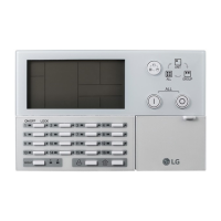
[Load Current Derating Curve]
☞ Note: Despite the motor current changing frequently due
to load fluctuation or acceleration and deceleration, the
inverter calculates the i
2
t and accumulates the value to
protect the motor.
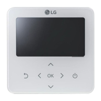
FU1-54: Overload Warning Level
FU1-55: Overload Warning Time
The inverter generates an alarm signal when the output
current has reached the FU1-54 [Overload Warning
Level] for the FU1-55 [Overload Warning Time]. The
alarm signal persists for the FU1-55 even if the current
has become the level below the FU1-54.
Multi-function output terminal (AXA-AXC) is used as the
alarm signal output. To output the alarm signal, set I/O
44 [Multifunction Auxiliary Contact Output] to ‘OL’.
☞ Note: Inverter is not tripped by this function.
☞ Note: The set value is the percentage of FU2-33 [Rated
Motor Current].
[Overload Warning]
FU1-56: Overload Trip Selection
FU1-57: Overload Trip Level
FU1-58: Overload Trip Delay Time
Inverter cuts off its output and displays fault message
when the output current persists over the FU1-57
[Overload Trip Level] for the time of FU1-58 [Overload
Trip Time]. This function protects the inverter and motor
from abnormal load conditions.
 Loading...