Chapter 6 - Parameter Description [FU2]
101
☞ Note: When the reference frequency is set inside the jump
frequency, the output frequency goes to the frequency
marked by “n” symbol.
☞ Note: If one frequency jump range is required, set all
ranges to the same range.
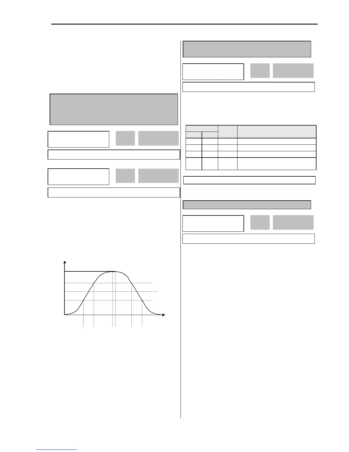
FU2-17: Start Curve for S-Curve Accel/Decel
Pattern
FU2-18: End Curve for S-Curve Accel/Decel
Pattern
This parameter is used to adjust the Accel and Decel
pattern when ‘S-Curve’ is selected in FU1-05 and FU1-
06 respectively. To use this function, the Reference
Frequency for Accel and Decel set in FU2-70 should be
set to ‘Delta freq’.
[S-Curve Adjustment]
Actual Accel Time = DRV-01 + (DRV-01 * FU2-17)/2 +
(DRV-01*FU2-18)/2
Actual Decel Time = DRV-02 + (DRV-02 * FU2-17)/2 +
(DRV-02*FU2-18)/2
Ex) If DRV-10: 1 sec, FU2-17: 40%, FU2-18: 20%,
Actual Accel Time = 1 sec + (1sec*0.4)/2 + (1sec*0.2)/2
= 1.3 sec
FU2-19: Input/Output Phase Loss Protection (Bit
Set)
This function is used to cut the inverter output off in case
of phase loss in either input power or inverter output.
FU2-19 [Phase Loss Protection Select]
Setting Range
1 0 10 Protect inverter from input phase loss
1 1 11
Protect inverter from input and output
phase loss
FU2-20: Power ON Start Selection
If FUN-20 is set to ‘No’, restart the inverter by cycling the
FX or RX terminal to CM terminal after power has been
restored.
If FUN-20 is set to ‘Yes’, the inverter will restart after
power is restored. If the motor is rotating by inertia at the
time power is restored, the inverter may trip. To avoid
this trip, use ‘Speed Search’ function by setting FU2-22
to ‘1xxx’.
FU2
?
Trip select
 Loading...