Chapter 6 - Parameter Description [FU2]
109
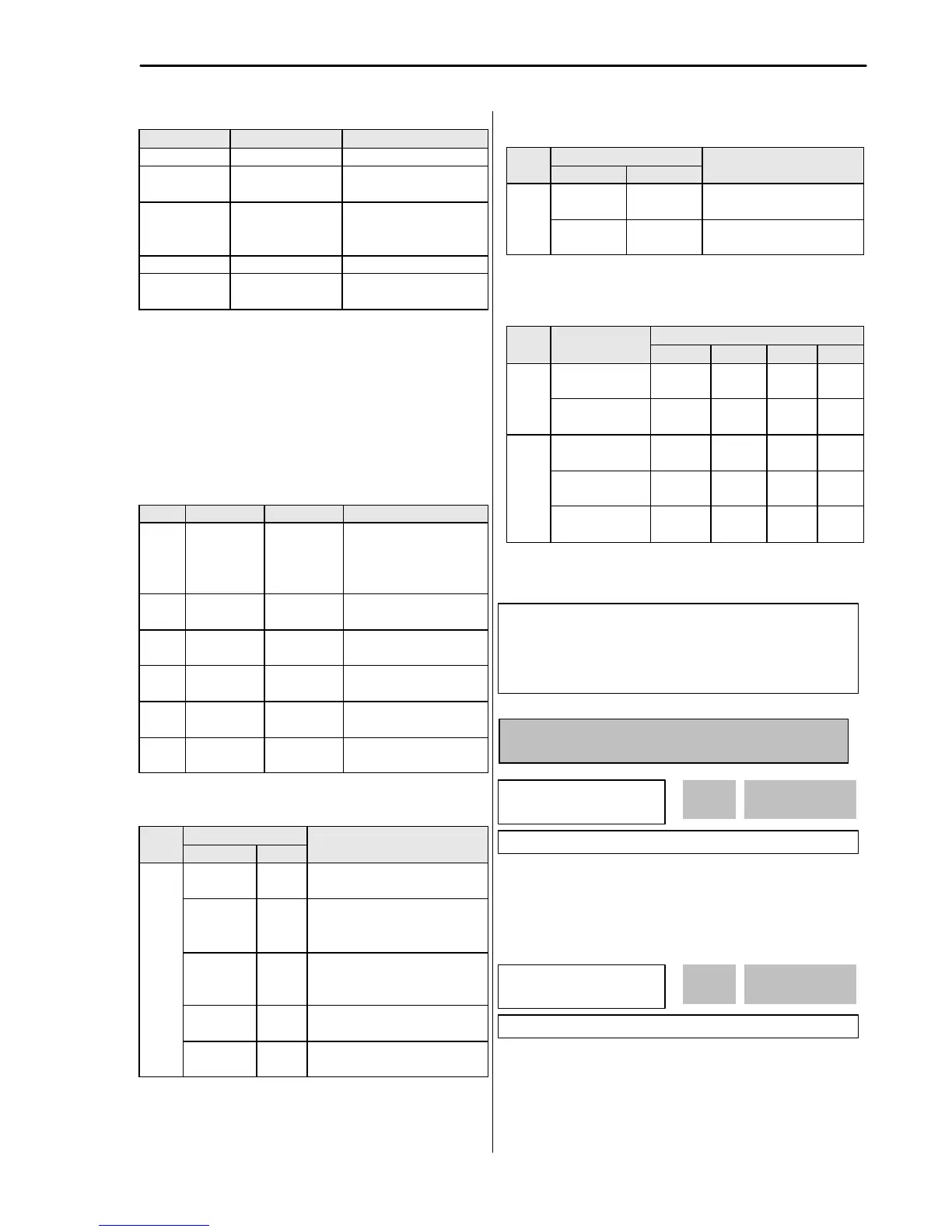
FU2-40 LCD display Description
0 No Auto-tuning disabled
1 All
Auto-tuning all
parameters
2 Rs + Lsigma
Stator resistance (Rs)
and Leakage inductance
(Lsigma) Auto-tuning
3 Enc Test PG status check
4 Tr
Rotor constant(Tr)
calculation
☞ Note 1: Ls and Noload-Curr are only valid during Motor
Rotation mode.
☞ Note 2: The motor constants values change with
temperature change, so auto tuning is to be conducted
after the temperature of the motor is stabilized.
☞ Note 3: The auto-tuning result could be different unless
LG motor is used.
☞ Note 4: The actual motor parameters (Rs, Rr, Lsigma,
Tr) can be used or set by user.
Code
Name Description
FU2-
34
Noload-Curr
No Load
Motor
Current
(RMS)
Setting and display the
No Load Motor Current
(RMS)
FU2-
40
Auto tuning
Auto-tuning enable
FU2-
41
Rs
Stator
resistance
Setting and display the
Stator resistance Rs
FU2-
42
Lsigma
Leakage
inductance
Setting and display the
Lsigma
FU2-
43
Ls
Stator
inductance
Setting and display the
Stator inductance Ls
FU2-
44
Tr
Rotor
constant
Setting and display the
Rotor constant Tr.
[Keypad display during Auto-tuning of motor parameters]
Display
Code
T1 Displayed during Stator
resistance (Rs) Auto-tuning
Lsigma
Tuning
T2 Displayed during Leakage
inductance (Lsigma) auto-
tuning.
Ls Tuning
T3 Displayed during Stator
inductance (Ls) and No-load
current auto-tuning.
ENC Test
T4 Displayed during Encoder auto-
tuning.
FU2-
40
Tr Tuning
T5 Displayed during Rotor filter
time constant (Tr) auto-tuning
[Keypad error display after Encoder test]
Display
Code
Description
Enc Err
T6 Displayed when incorrect
Encoder wiring error occurs
FU2-
40
Enc Rev
T7 Displayed when Encoder
wiring is connected reversly.
[Motor parameter display corresponding to inverter
capacity]
Motor parameter
Class
inverter
capacity
Rs Lsigma
Ls Tr
0.8[kW] ~
5.5[kW]
X.XXX
ohm
X.XX
mH
X.XX
mH
XXX
ms
200V
X.XXX
mH
X.XX
mH
XXX
ms
0.8[kW] ~
1.5[kW]
X.XX
ohm
X.X mH
18.5[kW] ~
75[kW]
X.X
mohm
XXX
ms
☞ Note: For 7-segment Keypad, parameter unit is not
displayed.
FU2-45: P Gain for Sensorless Control
FU2-46: I Gain for Sensorless Control
SL P-gain is the proportional gain of speed controller. If
this value is set high, you can get fast speed response
characteristic. However, if this value is set too high, the
steady state characteristics may become unstable.
SL I-gain is the integral gain of speed controller. If this
value is set low, you can get better transient response
characteristic and steady state characteristic. However,
if this value is set too low, there may be an overshoot in
speed control.
FU2
?
SL P-gain
45 1000
1000
Factory Default: 1000 1000
FU2
?
SL I-gain
46 100
100
30~37 [Motor related parameters]
FU2-39 [Control mode selection]
EXT-01 [Sub Board Type Display]
EXT-14 [Encoder Feedback Frequency]
EXT-15 [Pulse Input Signal Selection]
Morek IT OÜ, Rauna 24, 76506 Saue Harjumaa, Estonia. www.morek.eu Tel. +372 604 1423 Fax +372 604 1447 morek@morek.eu
 Loading...