Chapter 1 – Installation
14
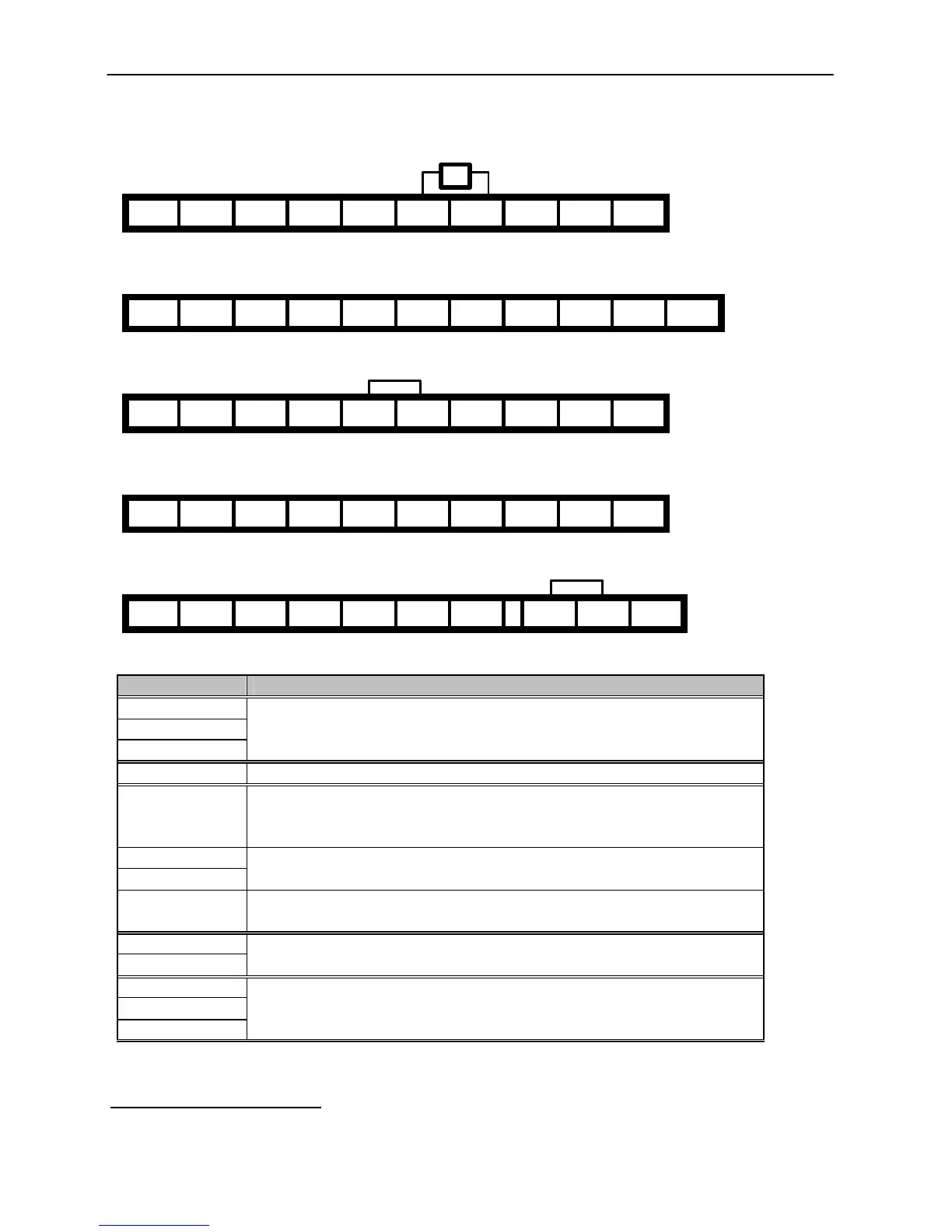
1.7 Power Terminals
n Type A Configuration: 1 ~ 5 HP (230/460/480V)
R S T G N B1 B2 U V W
n Type B Configuration: 7.5 ~ 10 HP (230/460/480V)
R S T G P N B1 B2 U V W
n Type C Configuration: 15 ~ 30 HP (230/460/480V)
R S T G P1 P2 N U V W
n Type C Configuration: 15 ~ 30 HP (230/460/480V), Built-in DBU model
R S T G P1 B1 B2 U V W
n Type D Configuration: 40~ 75 HP (230V), 40 ~ 100 HP (460/480V)
R S T G U V W
P1 P2 N
* Jumper should be removed to connect a DC reactor
Symbols Functions
R
S
T
AC Line Voltage Input
(3 Phase, 200 ~ 230VAC or 380 ~ 460/480 VAC)
G Earth Ground
P
Positive DC Bus Terminal
DB Unit (P-P
7
) Connection Terminals
(DB Unit may be added when more braking duty (More than 30%ED) is required)
P1
P2
External DC Reactor (P1-P2) and DB Unit (P2-N) Connection Terminals
N
Negative DC Bus Terminal
DB Unit (N-N
8
) Connection Terminal
B1
B2
Dynamic Braking Resistor (B1-B2) Terminals for 1-30HP inverters
U
V
W
3 Phase Power Output Terminals to Motor
(3 Phase, 200 ~ 230VAC or 380 ~ 460/480 VAC)
“Suitable for use on a circuit capable of delivering not more than 10,000 rms symmetrical amperes,
240 volts maximum for 230V class models and 480 volts maximum for 460V class models.”
7
This P terminal is provided on optional Dynamic Braking Unit.
8
This N terminal is provided on optional Dynamic Braking Unit.
DB Resistor integrated
Morek IT OÜ, Rauna 24, 76506 Saue Harjumaa, Estonia. www.morek.eu Tel. +372 604 1423 Fax +372 604 1447 morek@morek.eu
 Loading...