Chapter 6 - Parameter Description [APP]
150
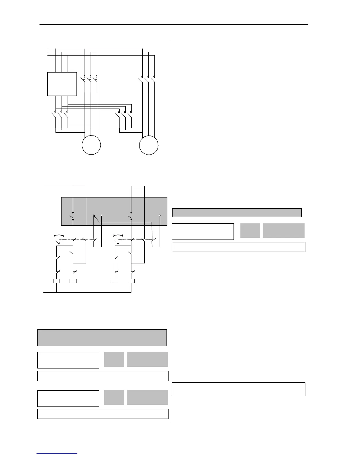
[Wiring Diagram for Inter-Lock Configuration]
[Sequence Circuit for Inter-Lock Configuration]
APP-27: Auto Change Time
APP-28: Auto Change Level
This function is used to protect motor from running alone
for a long time by changing operation to other motor.
Auto Change is accomplished when the following
conditions are satisfied:
1) The time set in APP-27 is over.
2) The actual value of controlling amount is less than the
value set in APP-28.
3) Only one motor is running.
When above three conditions are met, the inverter stops
the running motor, and changes motor to run by the
order set in APP-26. and then continues operation
according to new order.
If Auto Change Level (APP-28) is set to ‘0’, the function
is initiated only when the motor is in Stop or Sleep state.
The count time for Auto Change is depend on Auto
Change Mode (APP-26). In mode ‘0’, inverter starts
counting only when auxiliary motor is running. In mode
‘1’ or ‘2’, inverter starts counting when any motor is
running including main motor.
APP-29: Inter-Lock Selection
By setting this code to ‘Yes’, the multi-function input
terminals (P1 ~ P4) are used as auxiliary motor
operating condition of RLY1, RLY2, RLY3, and AUX.
The multi-function input terminal should be turned on to
run the corresponding auxiliary motor. If running with
any multi-function input terminal open with this function,
the inverter starts motors except the corresponding
motor. If multi-function input happens to be turned off
during motor running, the inverter stops all running
motors and restarts running with only normal motors
except the subject motor. By setting this parameter to
‘Yes’, the multi-function input terminals (P1~P4) are set
to ‘Interlock1’ through ‘Interlock4’ automatically.
☞ Note: P1 through P4 cannot be used for other purpose it
this code is set to ‘Yes’.
 Loading...